
Novel laser deflection scanning device and control method

A technology of deflection scanning and device control, which is applied in the direction of optics, optical components, instruments, etc., to achieve the effects of simple operation, reduced number of reflections, and increased deflection speed

Pending Publication Date: 2022-06-10
BEIFANG UNIV OF NATITIES
View PDF1 Cites 0 Cited by
  • Summary
  • Abstract
  • Description
  • Claims
  • Application Information

AI Technical Summary

Problems solved by technology

[0003] The object of the present invention is to provide a novel laser deflection scanning device and control method, which solves the problem that the laser deflection scanning angle is small in the prior art, and has a simple structure , the beneficial effect of large deflection scanning angle and effectively improving the deflection speed of the laser

Method used


Image

  • Novel laser deflection scanning device and control method
  • Novel laser deflection scanning device and control method

Examples


Embodiment 1

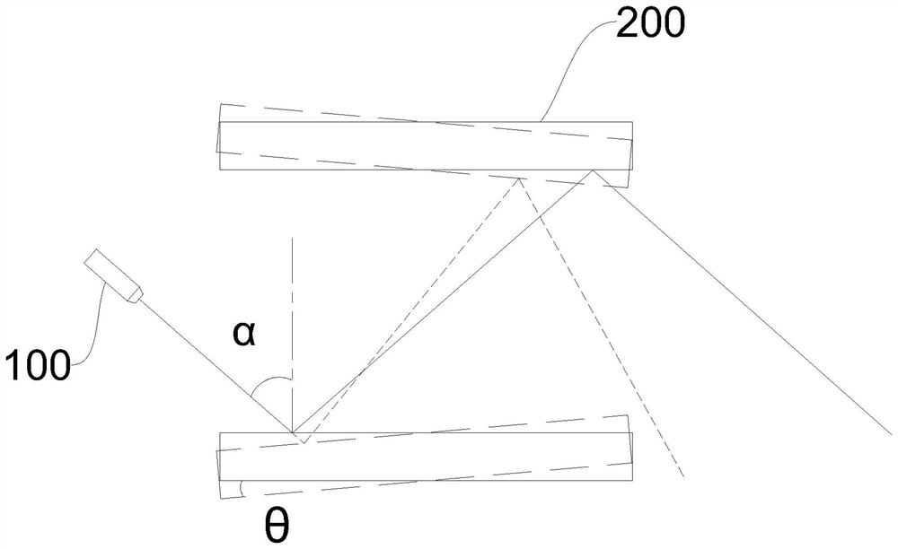
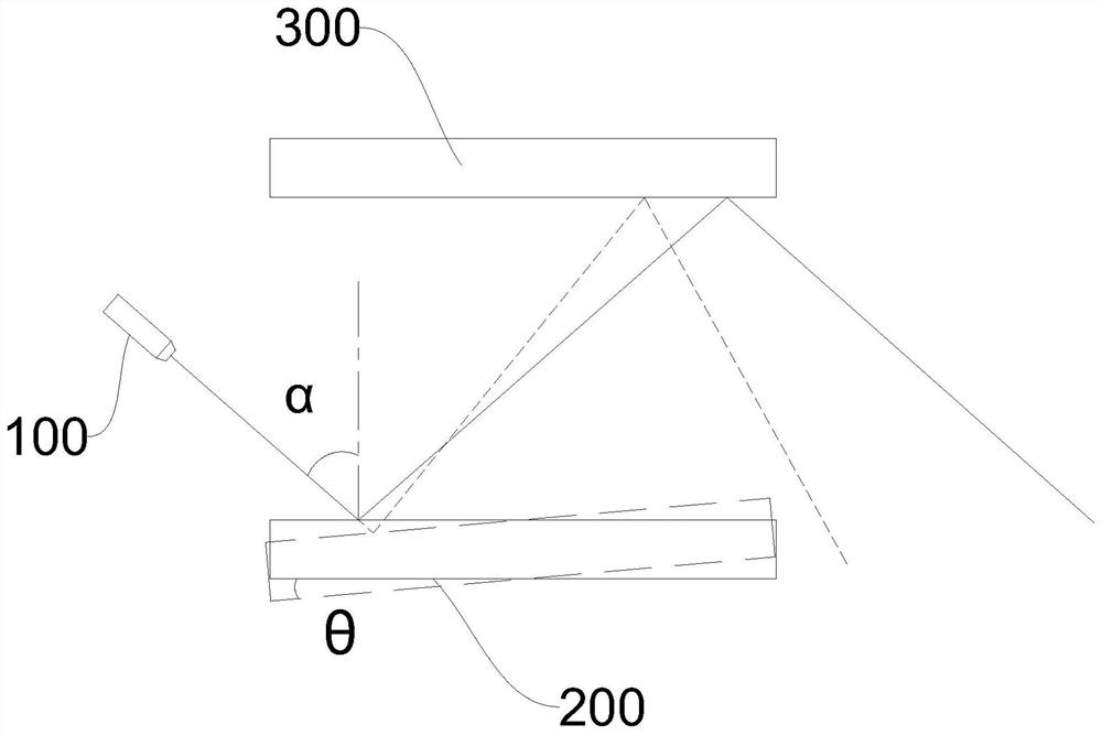
[0029] A novel laser deflection scanning device control method is characterized in that it comprises the following steps:

[0030] The two laser deflecting galvanometers 200 start to work through the control system, and the deflection directions of the two laser deflecting galvanometers 200 are opposite and maintain the same deflection angle amplitude.

[0031] Example 2

[0032] The above-mentioned embodiments of the present invention focus on the differences between the various embodiments. As long as the different optimization features of the various embodiments do not contradict each other, they can be combined to form a better embodiment. Considering the brevity of the text, here No longer.

[0033] The specific embodiments described above have further described the purpose, technical solutions and beneficial effects of the present invention in detail. It should be understood that the above descriptions are only specific embodiments of the present invention and are not i...

Embodiment 2


PUM


Abstract

The invention discloses a novel laser deflection scanning device which comprises a laser, two laser deflection galvanometers and a control system, the two laser deflection galvanometers are oppositely arranged, and the laser and the laser deflection galvanometers are both connected with the control system; in addition, the invention further discloses a control method of the novel laser deflection scanning device. The device has the beneficial effects that the structure is simple, the deflection scanning angle is large, and the deflection speed of laser is effectively improved.

Description

technical field [0001] The invention relates to the technical field of laser control, in particular to a novel laser deflection scanning device and a control method. Background technique [0002] Beam deflection technology is the technology to precisely control the laser beam, which plays a vital role in many optical and photonic applications, such as lidar, holographic storage system, optical information storage and processing, projection display and free space optical communication, etc. ; At present, the most widely used beam deflection device adopts the traditional mechanical scanning method, which is based on mirrors, prisms or lenses to achieve beam deflection, and can achieve a large deflection angle, but due to its mechanical system is too The shortcomings of complex and bulky, high energy consumption, high maintenance cost, slow scanning speed, low flexibility and reliability have limited its application in aerospace, communication and military fields. With the dev...

Claims


Application Information

Patent Timeline
Patent Type & Authority Applications(China)
IPC IPC(8): G02B26/10
CPCG02B26/105
Inventor 张白韩鑫洋江振青曹威张宏信许有志
Owner BEIFANG UNIV OF NATITIES
Learn More