Display panel, method for producing the same, and display device
A technology for display panels and substrates, applied in the fields of instruments, nonlinear optics, optics, etc., can solve the problems of increasing the power consumption of display panels, increasing the reliability of related circuits/chips, etc. Effect of driving voltage
- Summary
- Abstract
- Description
- Claims
- Application Information
AI Technical Summary
Problems solved by technology
Method used
Image
Examples
no. 1 example
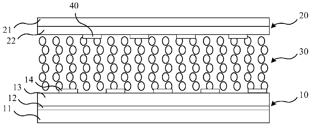
[0045] image 3 It is a schematic structural diagram of the first embodiment of the display panel of the present invention, Figure 4 for image 3 Schematic illustration of the formation of a multidimensional electric field by the shown structure. Such as image 3As shown, the main structure of the display panel provided in this embodiment includes an array substrate 10 and a color filter substrate 20 that are boxed together. The liquid crystal 30 is filled between the array substrate 10 and the color filter substrate 20 . The pixel electrode 14 is used as the upper slit electrode of the array substrate 10 , and the additional electrode 40 is formed on the color filter substrate 20 . Specifically, the array substrate 10 includes a substrate 11, a thin film transistor (not shown), a common electrode 12, an insulating layer 13 and a pixel electrode 14 sequentially formed on the substrate 11, the common electrode 12 serves as a lower electrode, and the pixel electrode 14 serve...
no. 2 example
[0060] The main structure of the display panel provided by this embodiment is the same as that of the first embodiment, including an array substrate and a color filter substrate assembled in a box, liquid crystals are filled between the array substrate and the color filter substrate, and the array substrate includes a substrate and sequentially formed The thin film transistor, common electrode, insulating layer and pixel electrode on the substrate, the common electrode is used as the lower layer electrode, the pixel electrode is used as the upper layer slit electrode, and an additional electrode is formed on the color filter substrate, wherein the additional electrode is a strip for applying a common voltage The transparent electrode is used to form an additional electric field with the pixel electrode on the array substrate as the upper slit electrode, so as to drive the liquid crystal in the vicinity of the color filter substrate to achieve normal deflection. Figure 7 It is ...
no. 3 example
[0068] The main structure of the display panel provided by this embodiment is the same as that of the first embodiment, including an array substrate and a color filter substrate assembled in a box, liquid crystals are filled between the array substrate and the color filter substrate, and the array substrate includes a substrate and sequentially formed The thin film transistor, common electrode, insulating layer and pixel electrode on the substrate, the common electrode is used as the lower layer electrode, the pixel electrode is used as the upper layer slit electrode, and an additional electrode is formed on the color filter substrate, wherein the additional electrode is a strip for applying a common voltage The transparent electrode is used to form an additional electric field with the pixel electrode as the upper slit electrode on the array substrate, so as to drive the liquid crystal in the vicinity of the color filter substrate to achieve normal deflection. Figure 8 It is ...
PUM
| Property | Measurement | Unit |
|---|---|---|
| width | aaaaa | aaaaa |
| width | aaaaa | aaaaa |
Abstract
Description
Claims
Application Information
 - R&D
- Intellectual Property
- Life Sciences
- Materials
- Tech Scout
- Unparalleled Data Quality
- Higher Quality Content
- 60% Fewer Hallucinations
Browse by: Latest US Patents, China's latest patents, Technical Efficacy Thesaurus, Application Domain, Technology Topic, Popular Technical Reports.
© 2025 PatSnap. All rights reserved.Legal|Privacy policy|Modern Slavery Act Transparency Statement|Sitemap|About US| Contact US: help@patsnap.com


