

Electroluminescent (EL) devices
- Summary
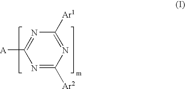
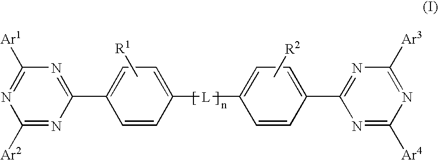
- Abstract
- Description
- Claims
- Application Information
AI Technical Summary
Benefits of technology
Problems solved by technology
Method used
Image


Examples
example i
Synthesis of 4,4'-Bis-[2-(4,6-diphenyl-1,3,5-triazinyl]-1,1'-biphenyl
In a 100 milliliter round bottom flask there was added 4,4'-biphenyidicarbonyl chloride (5.14 grams), 1,2-dichlorobenzene (150 milliliters), thionyl chloride (2.0 milliliters), and aluminum chloride (5.5 grams) with stirring, and benzonitrile (7.6 grams) was added slowly; and the resulting reaction mixture was heated under argon to about 150.degree. C. for 0.5 hour. The temperature of the reaction mixture was reduced to 120.degree. C., then ammonium chloride (3.5 grams) was added in one portion. The reaction mixture resulting was stirred at 150.degree. C. for an additional 20 hours. The reaction flask was removed from the heater and cooled to room temperature, about 25.degree. C. throughout. The resulting mixture was poured into 600 milliliters of methanol and stirred for 20 minutes, and the precipitates were collected by filtration and dried in a vacuum oven to afford 2.7 grams of crude product which was further p...
example ii
Synthesis of 4,4'-Bis-[2-(4,6-di-p-tolyl-1,3,5-triazinyl)]-1-1,1'-biphenyl
In a 250 milliliter round bottom flask there was added 4,4'-biphenyldicarbonyl chloride (8.215 grams), 1,2-dichlorobenzene (65 milliliters), thionyl chloride (1.0 milliliter), and aluminum chloride (7.3 grams). With stirring, p-tolunitrile (13.5 grams) was added slowly, and the resulting reaction mixture was heated under argon to about 150.degree. C. for 0.5 hour. The temperature of the reaction mixture was reduced to 150.degree. C., then ammonium chloride (7.13 grams) was added in one portion. The reaction mixture was stirred at this temperature for an additional 20 hours. The reaction flask was removed from the heater and cooled to room temperature. The mixture was poured into 600 milliliters of methanol and stirred for 20 minutes. The precipitates were collected by filtration and dried in a vacuum oven to afford 3.49 grams of crude product which was further purified by sublimation. The pure about 99.5 triaz...
example iii
Synthesis of 4,4'-Bis-[2-(4,6di-m-tolyl-1,3,5-triazinyl)-1-1,1'-biphenyl
In a 200 milliliter round bottom flask there was added 4,4'-biphenyldicarbonyl chloride (8.0 grams), 1,2-dichlorobenzene (65.0 milliliters), thionyl chloride (1.6 milliliters), and aluminum chloride (7.6 grams). With stirring, m-tolunitrile (13.4 grams) was added slowly, and the resulting reaction mixture was heated under argon to about 150.degree. C. for 0.5 hour. The temperature of the reaction mixture was reduced to 120.degree. C., then ammonium chloride (6.1 grams) was added in one portion. The reaction mixture was stirred at 150.degree. C. for additional 20 hours. The reaction flask was removed from the heater and cooled to room temperature, about 25.degree. C. throughout. The resulting mixture was poured into 100 milliliters of methanol and stirred for 20 minutes. The precipitates were collected by filtration and dried in a vacuum oven to afford 2.568 grams of crude product which was further purified by su...
PUM
| Property | Measurement | Unit |
|---|---|---|
| Percent by mass | aaaaa | aaaaa |
| Thickness | aaaaa | aaaaa |
| Thickness | aaaaa | aaaaa |
Abstract
Description
Claims
Application Information