Luminescent device

a technology of luminescent devices and carriers, applied in the direction of discharge tube luminescnet screens, natural mineral layered products, transportation and packaging, etc., can solve the problems of further reduction of drive voltage, difficult to generate noise, and unresolved carrier moving quality of organic interfaces, etc., to improve the mobility of carriers, reduce drive voltage, and prolong service life

Inactive Publication Date: 2009-08-11
SEMICON ENERGY LAB CO LTD
View PDF126 Cites 187 Cited by
  • Summary
  • Abstract
  • Description
  • Claims
  • Application Information

AI Technical Summary

Benefits of technology

[0025]Hereupon, the invention has its object to provide an organic luminescent element, which makes the best use of an advantage (functional separation) in a laminated structure used in the related art and enhances mobility of a carrier by mitigating an energy barrier present in an organic compound layer, and which is lower in drive voltage and longer in service life than those in the related art.
[0026]In particular, the invention has its object to remove organic interfaces present in an organic compound layer and enhance mobility of carriers by manufacturing an element of different concept from that of the conventionally used laminated structure, in which carriers in a luminescent layer are blocked for recombination, and at the same time to realize functions (referred below to as “functional realization”) of a plurality of various materials in the same manner as in functional separation involved in the laminated structure. Thereby, the invention has its object to provide an organic luminescent element, which is lower in drive voltage and longer in service life than those in the related art.
[0027]Further, the invention has its object to provide a luminescent device, which makes use of such organic luminescent element to thereby be lower in drive voltage and longer in service life than in the related art. Further, the invention has its object to provide an electric appliance, which is manufactured by the use of such luminescent device to thereby be lower in power consumption and more durable than in the related art.

Problems solved by technology

Further, since the organic luminescent element is a carrier-filling type luminescent element, it can be driven by DC voltage, and is hard to generate noise.
That is, in order to have the single-layered organic luminescent element efficiently emitting light (or driving at low voltage), it is necessary to use a material (referred below to as “bipolar material”) capable of carrying both electrons and holes in well-balanced manner, and Alq3 does not meet such requirement.
However, being a junction between substances of different kinds (in particular, a junction between insulating materials), the laminated structure described above will necessarily produce an energy barrier at an interface the substances.
Since the presence of an energy barrier inhibits movements of a carrier at the interface, the two following problems are caused.
One of the problems is that it results in a barrier leading to further reduction of drive voltage.
However, there is a field, in which the carrier moving quality of an organic interface has not been solved, and which presents an important point for coming level with a low drive voltage in the single layer structure making use of a bipolar material.
Further, the other problem caused by an energy barrier is believed to be an influence on the service life of organic luminescent elements.
That is, movements of a carrier are impeded, and brilliance is lowered due to build-up of charges.

Method used


Image

  • Luminescent device
  • Luminescent device
  • Luminescent device

Examples


embodiment 1

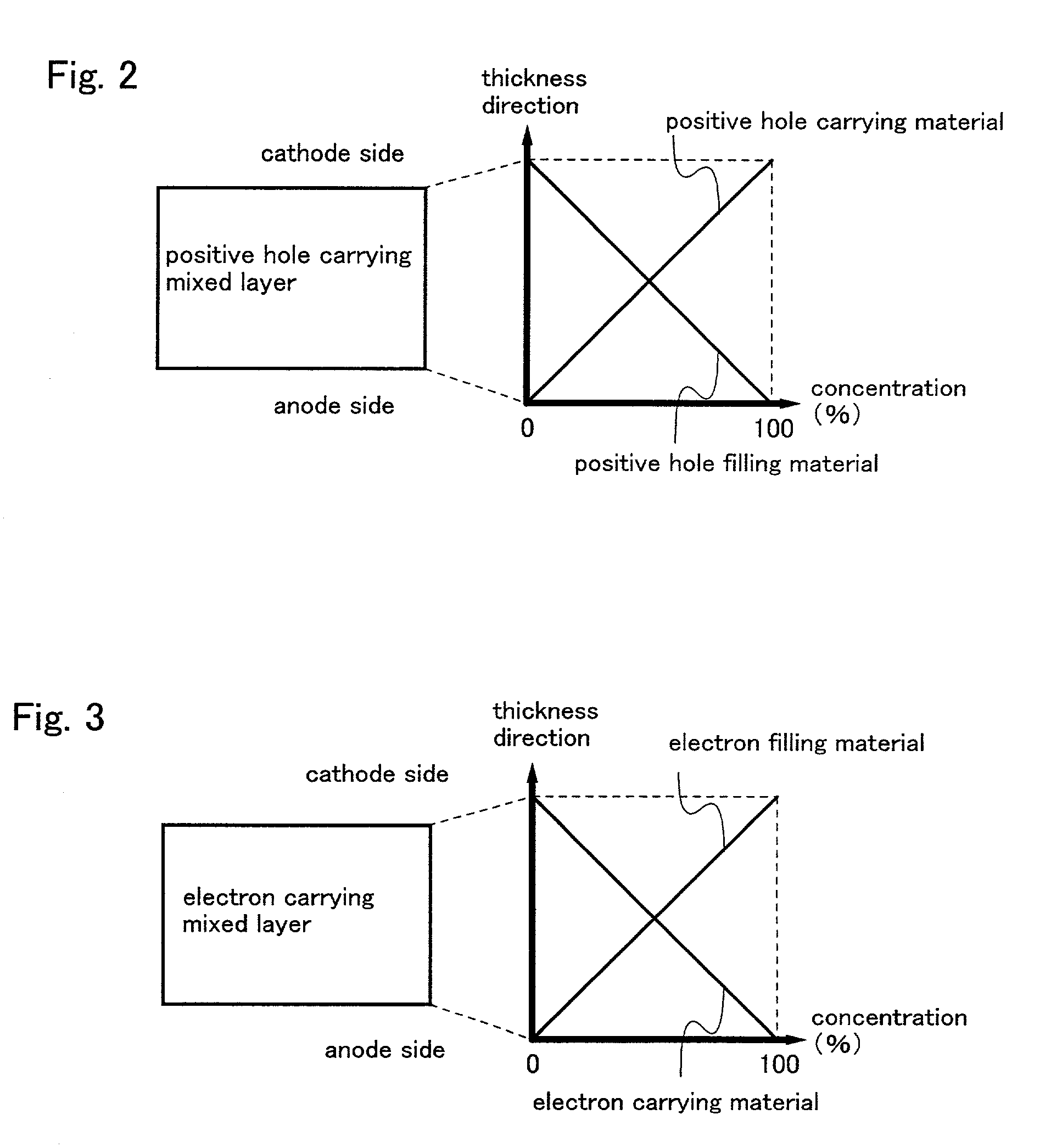
[0189]In this embodiment, there is concretely illustrated an element, to which the hole transporting mixed layer shown in FIG. 5 is applied.

[0190]First, an indium tin oxide (referred below to as “ITO”) is deposited to a film thickness of about 100 nm on a glass substrate 501 with sputtering to provide an anode 502. Subsequently, CuPc being a hole injecting material, and α-NPD being a hole transporting material, are subjected to codeposition at the deposition rate ratio 1:1 to form a hole transporting mixed layer 503, which has a film thickness of 50 nm.

[0191]Further, a layer obtained by doping rubrene of 5 wt % on Alq3 is laminated by a film thickness of 10 nm to provide a luminescent layer 504. Finally, Alq3 is deposited to a film thickness of 40 nm to provide an electron transporting layer 505, and Al:Li alloy (Li of 0.5 wt % in mass ratio) is deposited to a film thickness of about 150 nm to provide a cathode 506, so that it is possible to manufacture an organic luminescent elemen...

embodiment 2

[0192]In this embodiment, there is concretely illustrated an element, to which the electron transporting mixed layer shown in FIG. 6 is applied.

[0193]First, ITO is deposited to a film thickness of about 100 nm on a glass substrate 601 with sputtering to provide an anode 602. Subsequently, α-NPD being a hole transporting material is deposited to a film thickness of 50 nm to thereby form a hole transporting layer 603.

[0194]Further, perylene is laminated by a film thickness of 10 nm to provide a luminescent layer 604, and then BPhen being an electron transporting material, and Alq3 being an electron injecting material, are subjected to codeposition at the deposition rate ratio 1:1 to form an electron transporting mixed layer 605, which has a film thickness of 40 nm. Finally, Al:Li alloy (Li of 0.5 wt % in mass ratio) is deposited to a film thickness of about 150 nm to provide a cathode 606, so that it is possible to manufacture an organic luminescent element of blue luminescence result...

embodiment 3

[0195]In this embodiment, there is concretely illustrated an organic luminescent element obtained by inserting between an anode 2402 and an organic compound layer 2403, a hole injecting region, which is composed of a hole injecting material, in the organic luminescent element shown in FIG. 24.

[0196]First, a glass substrate 2401 is prepared, on which ITO is deposited to a film thickness of about 100 nm with sputtering to form an anode 2402. The glass substrate 2401 having the anode 2402 is carried into a vacuum chamber as shown in FIGS. 31A and 31B. In the embodiment, four kinds of materials (of which three kinds are organic compounds and one kind is a metal forming a cathode) are deposited, and so four deposition sources are necessary.

[0197]First, CuPc being a hole injecting material is deposited to a film thickness of 20 nm, and without an interval from a point of time when the film thickness of 20 nm is reached and deposition of CuPc is terminated, deposition of α-NPD being a hole...


PUM

PropertyMeasurementUnit
thicknessaaaaaaaaaa
thicknessaaaaaaaaaa
luminanceaaaaaaaaaa

Abstract

Interfaces between layers in a light emitting element are eliminated by using a light emitting element with a mixed region including a hole transporting material and an electron transporting material The light emitting element may further comprise a region with a dopant. By using this light emitting element, an organic luminescent element of low power consumption and long life is achieved, and the light emitting element can be used to manufacture a luminescent device and an electric appliance.

Description

FIELD OF THE INVENTION[0001]The invention relates to a luminescent device using an organic luminescent element having an anode, a cathode, and a film (referred below to as “organic compound layer”), which includes an organic compound adapted to effect luminescence upon application of an electric field. In particular, the invention relates to a luminescent device using an organic luminescent element, which is lower in drive voltage and longer in service life than a prior one. In addition, the luminescent device described in the specification of the present application indicates an image display device or a luminescent device, which use an organic luminescent element as luminescent element. Also, the luminescent device includes all of modules, in which a connector, for example, an anisotropic electroconductive film (FPC:Flexible printed circuit) or a TAB (Tape Automated Bonding) tape or a TCP (Tape Carrier Package) is mounted to an organic luminescent element, modules, in which a prin...

Claims


Application Information

Patent Timeline
Patent Type & Authority Patents(United States)
IPC IPC(8): H01J1/62B32B7/02H01J29/08H05B33/18H01L51/00H01L51/50H05B33/12H05B33/22
CPCH01L51/002H01L51/5012Y10T428/265Y10T428/26Y10T428/24942Y10S428/917H10K71/30H10K50/11H10K50/12H10K50/15H10K50/17
Inventor SEO, SATOSHIYAMAZAKI, SHUNPEI
Owner SEMICON ENERGY LAB CO LTD
Why Eureka
Try Eureka