Optical-deflection accelerating device

a technology of optical deflection and accelerating device, which is applied in the direction of condensers, mirrors, instruments, etc., can solve the problems of high cost, complex structure of the device thereof, and difficulty in achieving the multiplied acceleration of the rotating speed of the rotating mirror

Active Publication Date: 2012-12-18
SHENZHEN UNIV
View PDF4 Cites 0 Cited by
  • Summary
  • Abstract
  • Description
  • Claims
  • Application Information

AI Technical Summary

Benefits of technology

[0009]The present invention relates to an optical-deflection accelerating device which can solve the problem of the conventional technology, and obtain any multiplier of deflecting acceleration of a light-beam.
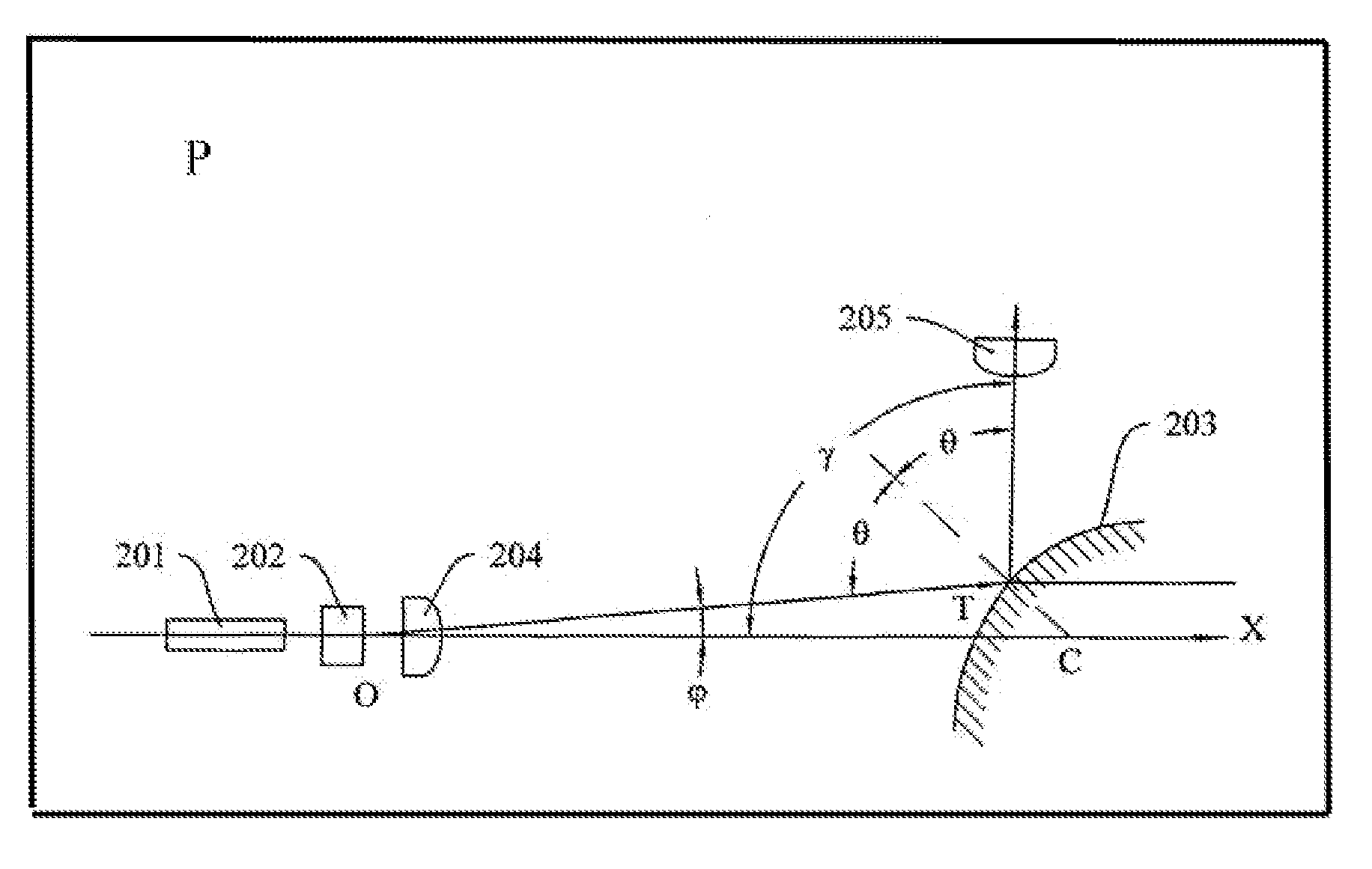
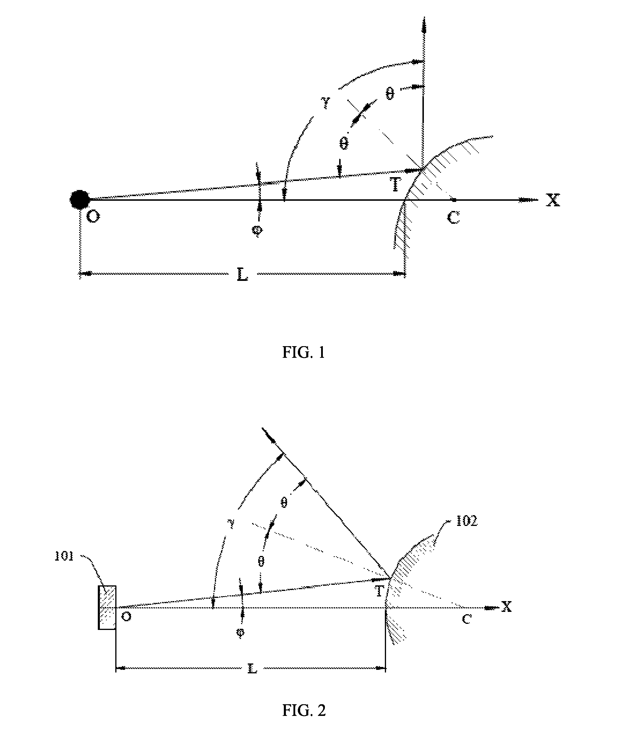
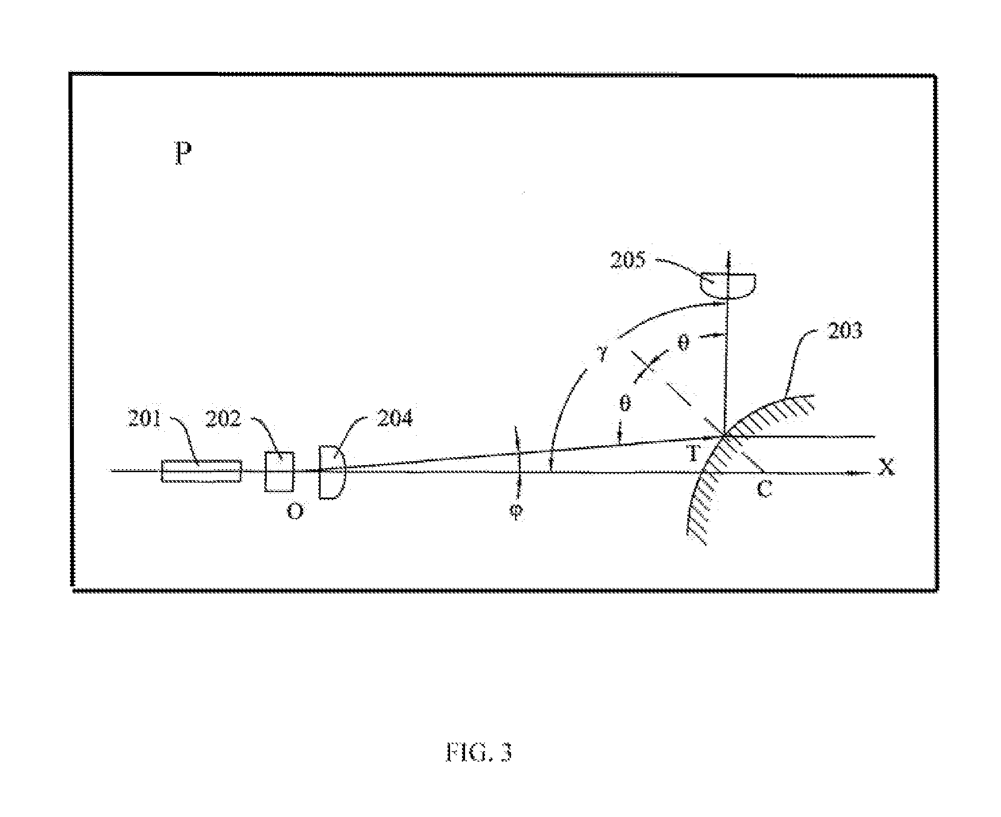
[0020]The optical-deflection accelerating device of the present invention has many advantages described as follows. Since the reflective device of the optical-deflection accelerating device is a curved-surface reflective mirror, when the incident light-beam enters into a certain point of the curved-surface reflective mirror, an incident angle of the incident light-beam is equal to a reflective angle of the emergent light-beam based on the law of reflection, and the incident angle and the reflective angle are increased along with variation of the location of the reflective point on the curved-surface reflective mirror or an increasing curvature. When the incident light-beam is deflected, the emergent light-beam is also deflected therewith and the deflection angle is enlarged. Thus, the present invention can adjust the curvature of the curved-surface reflective mirror, as needed, to obtain different multiplying factors for accelerating deflection. It is a novel method different from the general two methods of the conventional technology for improving the deflection-accelerating multiplying factor of the light-beam, which are employing the rotating mirror to reflect and improving the rotating speed of the rotating mirror; or accurately locating the two opposite reflective mirrors and increasing the reflecting amount therebetween to improve the deflection-accelerating multiplying factor of the light-beam. Furthermore, the optical-deflection accelerating device is very suitable for a tiny angle of the electrical-optical deflection and a tiny displacement generated by the Goos-Hänchen displacement to accelerate deflection of the light-beam. The process of accelerating deflection of the light-beam is generally in a nanosecond magnitude, and time of the transient process is a relaxation time of the electro-optical effect.
[0021]Since the optical-deflection accelerating device of the present invention does not require any mechanical rotating device or reflective mirrors that are accurately located in order to conduct multiple reflections, it has a simple structure. The present invention alters the curvature of the curved-surface reflective mirror to obtain 10 times or more than 10 times of optical-deflection acceleration to improve the deflection speed of the emergent light-beam. Thus the deflection speed of the light-beam can be improved 1˜2 orders of magnitude, thus greatly improving scan speed of the light-beam deflection device, photographic frequency, amount of the spatio-temporal information, and satisfying needs of researching the transient process, such as detonation process or shock-wave process, etc., and particularly satisfying the needs of scientific research in extreme condition, such as top-speed laser fly die or Z-pinch, etc.

Problems solved by technology

A speed of deflecting the incident light-beams is a major issue related to performance of photography using the rotating mirror.
But this method is difficult to achieve multiplied acceleration of the rotating speed of the rotating mirror (HIGH POWER LASER AND PARTICLE BEAMS, 2006, 18(6):1277˜1281; SPIE, 2005, Vol. 5638:117˜123).
However, the method of multi-reflection must be performed by accurate calculation, and the device thereof comes with a complex structure and a high cost.

Method used


Image

  • Optical-deflection accelerating device
  • Optical-deflection accelerating device
  • Optical-deflection accelerating device

Examples


Embodiment Construction

[0029]Reference will now be made to the drawings to describe exemplary embodiments of the present optical-deflection accelerating device in detail. The following description is given by way of example, and not limitation.

[0030]In the present invention, light-beams with tiny deflections or displacements are sequentially projected into different locations of a spatial curved surface for forming different incident angles. Based upon the reflection law, reflective angles of emergent light-beams and incident angles of incident light-beams are equal and continuously change. Degrees of the reflective angles and a change range of the reflective angles are limited by relative locations of the incident light-beams and the curved surface, and a curvature of the curved surface. Thus, they may be adjusted in design. Therefore, the invention achieves scanning of the emergent light-beams and enlarging in deflection angles. An acceleration multiplying factor is related to structural parameters, suc...


PUM


Abstract

An optical-deflection accelerating device is provided. The device comprises an incident light source for generating an incident light-beam with a deflection speed, an emergent-light capturing device for capturing an emergent light-beam, and a reflective device which is a curved-surface reflective mirror for reflecting the incident light-beam to the emergent-light capturing device. When the incident light-beam enters to a reflective point on the curved-surface reflective mirror in sequence, an incident angle and a reflective angle are altered with locations of the reflective point on the curved-surface reflective mirror, and are increased with an increased curvature of the reflective point. When the incident light-beam is deflected with a tiny initial deflection angle, the reflective light-beam is deflected therewith and the deflection angle is enlarged. The curvature of the curved-surface reflective mirror can be adjusted to obtain different accelerated deflections.

Description

[0001]This application claims priority to Chinese Patent Application No. 200910104978.1, filed on Jan. 19, 2009, which is hereby incorporated by reference.BACKGROUND[0002]1. Field of the Invention[0003]The present invention relates to ultra-high speed photography technology, and more particularly to an optical-deflection accelerating device in ultra-high speed photography technology.[0004]2. Description of the Related Technology[0005]To obtain spatio-temporal information in microsecond to nanosecond transient-varying processes, for example, information for researching detonation physical process and shock-wave physical process, ultra-high speed photography technology has been developed. The ultra-high speed photography technology can be used to obtain photos of a transient-process in a microsecond-to-nanosecond time interval for studying variation rules of the transient process. The key technology of the ultra-high speed photography technology is how to generate a high speed and how...

Claims


Application Information

Patent Timeline
Patent Type & Authority Patents(United States)
IPC IPC(8): G02B17/00G02B3/06G02B17/08
CPCG02B5/10G03B15/06G03B39/00G02B19/0085G02B19/0028
Inventor LI, JINGZHENWU, QINGYENG
Owner SHENZHEN UNIV
Why Eureka
Try Eureka