Chiral molecule detection device based on tapered fiber

A technology of chiral molecules and detection devices, which is applied in the field of chiral detection, can solve the problems of poor detection accuracy and precision, high beam alignment requirements, and poor portability, and achieve high accuracy and sensitivity and portability Strong, accurate results

Pending Publication Date: 2022-06-17
陕西帆瑞威光电科技有限公司
View PDF0 Cites 0 Cited by
  • Summary
  • Abstract
  • Description
  • Claims
  • Application Information

AI Technical Summary

Problems solved by technology

[0003] The publication number is "CN111751344A", and the patent application titled "Chirality Measuring Device for Measuring Chiral Molecules" provides an optical-based chiral molecular detection device, but the device is realized by optical path design, and it is used in many An optical device, the overall volume is large, it is not convenient to carry, and it has high requirements for beam alignment. In addit

Method used


Image

  • Chiral molecule detection device based on tapered fiber
  • Chiral molecule detection device based on tapered fiber
  • Chiral molecule detection device based on tapered fiber

Examples


Example Embodiment

[0028]实施例1

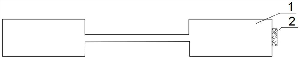
[0029]本发明提供了一种基于拉锥光纤的手性分子探测装置,如图1所示,该手性探测装置包括光纤1、反射层2、光纤环形器、光源、光探测器。反射层2为手性结构,反射层2固定设置于光纤1一端的端面上,光纤1的另一端为预留端,反射层2由镀膜或溅射工艺制备。光纤1为具有拉锥区域的光纤1,拉锥区域可以在光纤1中间位置,也可以靠近设置有反射层2的一端,还可以靠近光纤1的预留端;优选地,光纤1的拉锥区域在光纤1中间位置,或靠近设置有反射层2的一端,拉锥区域位于光纤1中间位置时,拉锥时两侧长度相等,更容易进行拉锥,方便制备,拉锥区域靠近设置有反射层2的一端时,这样拉锥区域距离光纤1预留端的距离较远,方便将其伸入手性分子溶液中,使得手性分子与拉锥区域的接触更充分。

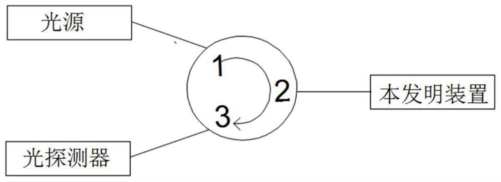
[0030]应用时还包括光源、光探测器、光纤环形器,如图2所示,光纤环形器有三个端口,端口1与光源连接,端口2与本发明装置中的光纤2的预留端连接,端口3与光探测器连接。探测时待测手性分子的溶液可以滴在拉锥区域,也可以将拉锥区域浸入手性分子溶液,还可以将光纤1设有反射层2的一端和拉锥区域一同伸入手性分子溶液,即需要手性分子溶液与拉锥区域接触。光源发出的激光由端口1进入光纤环形器,从端口2进入光纤1,在光纤1中以基模传输,由于基模沿光纤1中心轴传输,且不具有手性,经过拉锥区域时与手性分子溶液之间不产生相互作用,反射层2为手性结构,激光照射在手性结构上产生表面等离激元效应,经过反射层2反射后,不具有手性的基模形式变为手性电磁场,在直径较细的拉锥区域,手性电磁场靠近光纤1边缘传播,即在拉锥区域,手性电磁场靠近光纤1纤芯和包层的界面处传播,这样拉锥区域内传播的手性电磁场能够与拉锥区域外侧的手性分子产生相互作用,使得光纤内传播的手性电磁场的强度变化,即反射激光的反射系数变化,从而,根据反射激光的反射系数能够确定待测手性分子的手性。

[0031]拉锥区域的直径较细,且包层的厚度较薄,手性电磁场与手性分子之间的距离较近,从而相对较远处的手性分子与手性电磁场能够产生相互作用,且相互作用较强,同等条件下,能够与距离更远处的手性分子相互作用,使得手性分子与手性电磁场的作用距离较长,因此本发明装置探测手性分子时的作用距离较长。拉锥光纤与手性分子相互作用的长度较长,且拉锥光纤内传播的手性电磁场与手性分子的相互作用较强,同时拉锥光...

Example Embodiment

[0032]实施例2

[0033]在实施例1的基础上,光纤1为石英光纤,具体地,可以为单模石英光纤或多模石英光纤,光纤1为单模石英光纤时,传播激光的质量较好,传播距离也较长,适合远距离传输,方便进行远程手性探测;光纤1为多模石英光纤时,能够传输多种模式的激光,且多模石英光纤的包层较薄,在相同的拉锥工艺下,多模光纤内的手性电磁场更靠近光纤1的边缘,其内传播的手性电磁场与待测手性分子的距离更近,相互作用的距离也更长。光纤1拉锥区域的长度小于0.5cm,拉锥区域光纤1的截面直径为5μm-50μm,这样,既能得到不易损坏且粗细均匀长度较长的拉锥区域,还能够使得手性分子溶液与拉锥区域的接触更加充分,包层较薄,使得手性电磁场能够与手性分子之间产生较强的相互作用,同时一部分倏逝波泄露出包层,使得手性电磁场能够与手性分子之间产生更强的相互作用,从而更大地改变手性电磁场的强度,进而更多地改变反射激光的反射系数,从而本发明装置的探测精确度和灵敏度较高。

[0034]反射层2的材料为贵金属材料,具体地,反射层2的材料为金或银,这样,由于金或银对激光的反射性能较好,能够将更多的激光反射回光纤1内继续传播,使得手性电磁场的强度能够产生更多的变化,即反射激光的反射系数能够变化的范围更大,这样本发明装置能够探测的手性的范围更大,能够探测的手性分子的种类更多。反射层2的结构为手性结构,具体地,反射层2的结构可以为非对称的“L”、非对称的“A”、非对称的“T”等具有手性的结构,更具体地,反射层2的结构可以为单个的非对称的“L”、非对称的“A”、非对称的“T”等具有手性的结构,也可以为多个非对称的“L”、非对称的“A”、非对称的“T”等具有手性的结构,优选地,反射层2的结构为多个非对称的“L”、非对称的“A”、非对称的“T”等具有手性的结构,多个手性结构产生的手性电磁场的手性为单个手性结构产生的手性电磁场的叠加,多个手性结构可以相同也可以不同,优选地,反射层2为多个相同的手性结构的组合,这样,能够尽可能减小手性结构产生的手性电磁场之间的抵消,使得产生的手性电磁场的手性更强,这样,一方面,较强手性的手性电磁场与手性分子之间的相互作用更强,手性电磁场与手性分子相互作用时对手性电磁场的强度的改变更大,反射激光的反射系数的改变更大,因此,本发明装置探测手性的精确度和灵敏度较高;另一方面,更强的手性电磁场在拉...

Example Embodiment

[0036]实施例3

[0037]在实施例2的基础上,周期排布的手性结构需完全覆盖光纤1的纤芯部分,其覆盖面积至少略大于光纤1截面上纤芯的面积,这样,一方面能够确保大部分激光被反射层2反射回光纤1内继续传播,另一方面能够产生较强的手性电磁场。周期排布的手性结构的整体阵列的形状可以为圆形、矩形、三角形等任意形状,优选地,周期排布的手性结构的整体阵列的形状为圆形或矩形,方便制备。相邻手性结构的间距大于200nm,当相邻手性结构之间的距离小于等于200nm时,相邻的两个手性结构之间不会产生相互作用,手性结构之间的相互作用会使得手性电磁场的手性减弱,从而手性电磁场和手性分子之间相互作用时,对手性电磁场的强度的改变较小,从而会减小手性探测的精确度和灵敏度,因此相邻手性结构之间的距离需要大于200nm,才能保证相邻的手性结构之间没有相互作用。

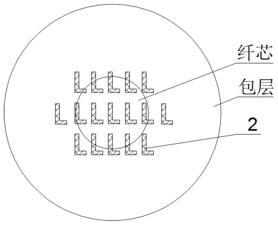
[0038]相邻手性结构的间距可以相同也可以不相同。如图3所示为相邻手性结构间距相同时的反射层2的示意图,相邻手性结构的间距相同时,手性结构的间距一致,制备时参数设置一致,一次可以制备完成,方便制备;同时由于反射层2的手性结构排布均匀,反射层2能够反射更多的激光,使得手性电磁场的强度能够产生更多的变化,即反射激光的反射系数能够变化的范围更大,这样本发明装置能够探测的手性的范围更大,能够探测的手性分子的种类更多。相邻手性结构的间距不相同时,优选地,靠近光纤1纤芯中间位置处的手性结构间距较小,靠近手性结构排布边缘处的手性结构间距较大,由于基模沿光纤1的轴线传播,即激光主要分布在靠近光纤1纤芯中间位置处,靠近边缘处的激光较少,因此,靠近光纤1纤芯中间位置处的手性结构与基模的相互作用较强,手性电磁场主要由靠近光纤1纤芯中间位置处的手性结构产生,这样中间有限的空间内能够设置更多的手性结构,从而在制备反射层2时贵金属材料的利用率较高的同时能够产生手性更强的手性电磁场,这样,一方面,较强手性的手性电磁场与手性分子之间的相互作用更强,手性电磁场与手性分子相互作用时对手性电磁场的强度的改变更大,反射激光的反射系数的改变更大,因此,本发明装置探测手性的精确度和灵敏度较高;另一方面,更强的手性电磁场在拉锥区域中传播时更靠近边缘,这样手性电磁场与手性分子之间的距离更近,相互作用的距离更长,需要的手性分子的量更少。

[0039]本实施例以非对称的“L”的手性结构为...


PUM

PropertyMeasurementUnit
Diameteraaaaaaaaaa
Thicknessaaaaaaaaaa
Particle sizeaaaaaaaaaa

Abstract

The invention relates to the field of chiral detection, and provides a tapered fiber-based chiral molecule detection device, the device comprises an optical fiber, a reflecting layer, a fiber circulator, a light source and a light detector, one section of the optical fiber is a tapered area, the reflecting layer is of a chiral structure and is fixedly arranged on the end face of one end of the optical fiber, the other end of the optical fiber is a reserved end, and the optical fiber circulator is arranged on the reserved end. The reserved end is connected with one port of the optical fiber circulator, the other two ports of the optical fiber circulator are connected with the light source and the optical detector respectively, and the connection mode of the optical fiber circulator meets the requirement that laser emitted by the light source enters the reserved end through the optical fiber circulator, and laser emitted from the reserved end enters the optical detector through the optical fiber circulator. The chirality of the chiral molecules has great influence on the light intensity of the reflected laser, that is, the difference of reflection coefficients of the reflected laser obtained by the two chiral molecules with small chirality characteristic difference is great, so that the device provided by the invention has high chirality detection accuracy and sensitivity.

Description

technical field [0001] The invention relates to the field of chiral detection, in particular to a chiral molecular detection device based on a tapered optical fiber. Background technique [0002] Hand shape refers to the property that a structure cannot coincide with its mirror image structure through in-plane translation and rotation. For example, our hands, the left hand and the mirror image of the right hand cannot overlap. Chirality is a ubiquitous phenomenon in nature and plays a vital role in life. Chiral molecules refer to molecules with a certain configuration or conformation that are different from their mirror images and cannot overlap each other. All chiral molecules are optically active, that is, there are special optical properties such as asymmetric transmission, circular dichroism, and circularly polarized luminescence. Active, and all molecules of optically active compounds are chiral molecules. Chiral molecules include asymmetric molecules without any ele...

Claims


Application Information

Patent Timeline
IPC IPC(8): G01N21/552
CPCG01N21/554
Inventor 杨丹李颖
Owner 陕西帆瑞威光电科技有限公司
Why Eureka
Try Eureka