
Linearization correction method and device for radio frequency receiver

A technology of radio frequency receiver and calibration method, applied in transmission systems, electrical components, etc., can solve the problems of incompetent broadband communication requirements and inability to guarantee, and achieve the effect of broad applicability and flexible use

Active Publication Date: 2022-06-21
CHENGDU UNIV OF INFORMATION TECH
View PDF23 Cites 0 Cited by
  • Summary
  • Abstract
  • Description
  • Claims
  • Application Information

AI Technical Summary

Problems solved by technology

Neither can guarantee the overall linear performance of the circuit after system integration
The linearization of the circuit mostly presents the characteristics of point frequency or narrowband, which cannot meet today's broadband communication needs

Method used


Image

  • Linearization correction method and device for radio frequency receiver
  • Linearization correction method and device for radio frequency receiver
  • Linearization correction method and device for radio frequency receiver

Examples


Embodiment Construction

[0092] In order to make the technical means, features and effects realized by the present invention easier to understand, the technical solutions in the embodiments of the present invention are clearly and completely described below with reference to the specific embodiments and the accompanying drawings in the embodiments of the present invention.

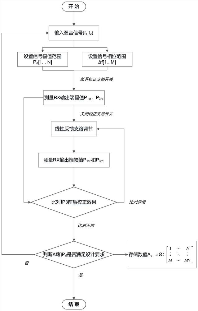
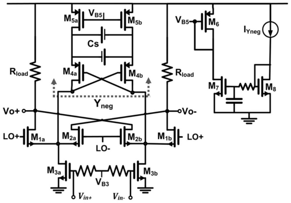
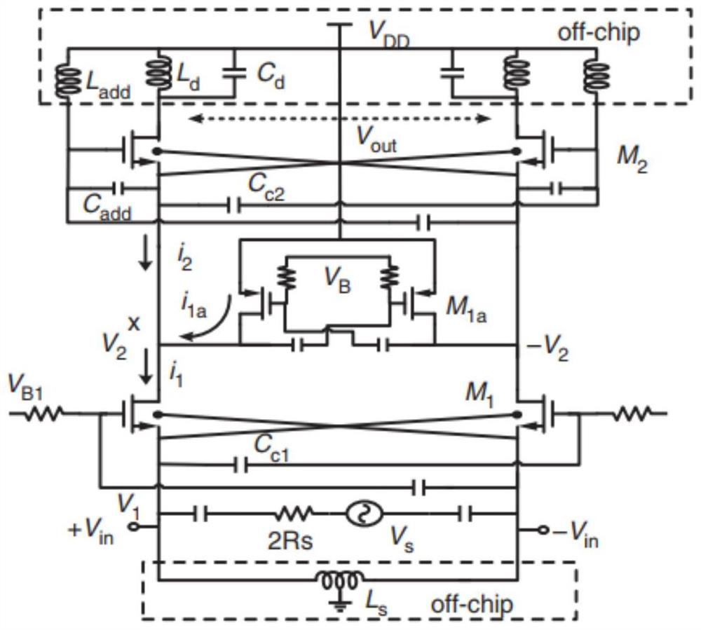
[0093] combine Figure 1-Figure 10 As shown, in order for those skilled in the art to better understand the principle of the present invention, the working principle of the radio frequency receiver linearization circuit proposed by the present invention is described as follows:

[0094] Image 6 A simplified block diagram of the linearization correction technique is given. It can be seen that the linearization scheme is implemented by adding an auxiliary path in parallel with the original receiver. Along the main path of signal transmission, it is the main channel of the receiver. Specifically, for the two-tone RF input signal,...


PUM


Abstract

The invention belongs to the technical field of radio frequency integrated circuits, and particularly relates to a linearization correction method and device for a radio frequency receiver. The device comprises a radio frequency receiver, an active combiner, a second-order intermodulation component generator, an amplitude regulator, a phase regulator, a baseband multiplier and an analog switch, an input differential radio frequency signal is amplified by the main path and the correction branch to obtain a differential linear baseband signal output; in the correction branch, an input radio-frequency signal is converted into a second-order intermodulation product by a second-order intermodulation component generator, amplitude and phase conditioning is carried out, and then multiplication operation is carried out on the second-order intermodulation product and an output signal of the main path receiver to obtain a conditioned third-order intermodulation distortion component; and the third-order intermodulation distortion component and a third-order distortion component in the output signal of the receiver are superposed by the active combiner and are counteracted in the final output signal. According to the invention, distortion in the signal is suppressed, a linear fundamental frequency item is improved, and a higher signal-to-noise ratio and a higher communication effect are realized.

Description

technical field [0001] The present invention relates to a linearization correction method and device, in particular to a linearization correction method and device of a radio frequency receiver. Background technique [0002] Intermodulation distortion and intermodulation distortion are usually present in communication circuits. [0003] Non-linear DUT (such as LNA, PA, tower amplifier), when multiple frequency signals are input, each spectral component will interact to generate new spectral components (spectral regeneration); when the input signal is small enough, the amplifier works online The intermodulation distortion will not deteriorate and keep at a relatively balanced level; as the power input to the DUT increases, the amplifier gradually enters the compression region, and the intermodulation distortion will deteriorate rapidly. [0004] Two or more signals of different frequencies generate new frequency components after passing through an amplifier or speaker. This ...

Claims


Application Information

Patent Timeline
Patent Type & Authority Applications(China)
IPC IPC(8): H04B1/10H04B1/12
CPCH04B1/10H04B1/12Y02D30/70
Inventor 郭本青廖星月樊润伍
Owner CHENGDU UNIV OF INFORMATION TECH
Learn More