


Quick Research
Generate reliable direction feasibility study reports for your R&D in just a few steps.

Technical Q&A
Discover and master advanced knowledge NOW. Basics, ideas, possibilities, all at once.

Find Solutions
As an expert in R&D theories, this can generate solutions to your technical problems instantly.

Evaluate Feasibility
Analyze your overall solution with one click, know your potential R&D risks in advance.

Monitor Landscape
Get weekly tech updates, stay abreast of the latest tech innovations and key insights.
Rotating electric machine
A technology for rotating electrical machines and rotors, applied to synchronous motors with stationary armatures and rotating magnets, electromechanical devices, electrical components, etc., can solve problems such as large magnetic resistance, and achieve the effect of reducing high-harmonic iron loss
- Summary
- Abstract
- Description
- Claims
- Application Information
AI Technical Summary
Problems solved by technology
Method used
Image

Examples
Embodiment approach 1
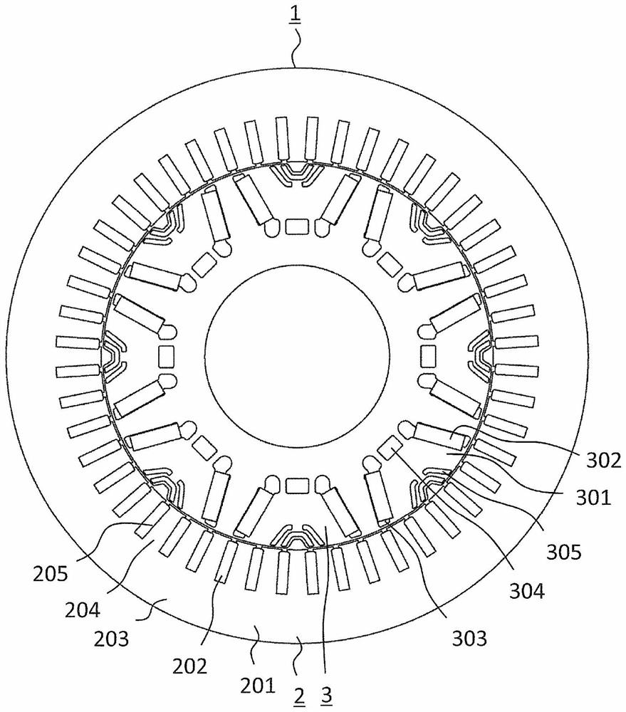
[0040] figure 1 It is a plan view showing the rotating electrical machine according to the first embodiment. The rotating electrical machine 1 is a permanent magnet type rotating electrical machine. The rotating electrical machine 1 includes a stator 2 and a rotor 3 that rotates with respect to the stator 2 . In this example, the axial direction refers to the direction along the axis of rotation of the rotor 3 , the radial direction refers to the radial direction centered on the axis of rotation of the rotor 3 , and the circumferential direction refers to the axis of rotation of the rotor 3 . the circumference. The rotor 3 is arranged radially inward with respect to the stator 2 . The rotor 3 rotates in the circumferential direction relative to the stator 2 .
[0041] The stator 2 includes a stator core 201 and a plurality of coils 202 provided in the stator core 201 . The stator core 201 includes a cylindrical core back 203 and a plurality of teeth 204 protruding radiall...
Embodiment approach 2
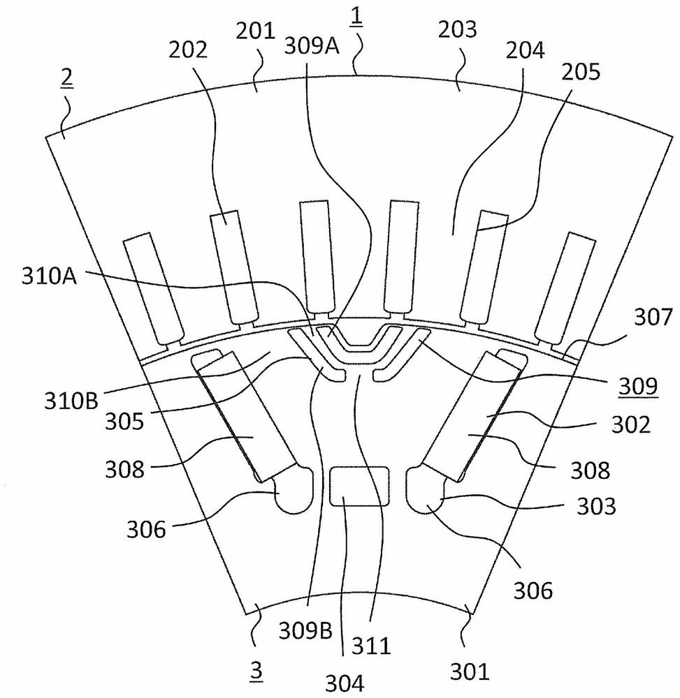
[0090] Figure 13 It is a plan view showing the main part of the rotor of the rotating electrical machine according to the second embodiment. exist Figure 13 In the figure, the part constituting one magnetic pole in the rotor 3 is shown. In the second magnetic slit 309B, the first magnet magnetic flux guide path 311 is arranged in the portion closest to the permanent magnet 308 . In Embodiment 2, the first magnet magnetic flux guide paths 311 are arranged at two locations of the second magnetic slit 309B. The magnetic flux from the permanent magnet 308 is guided to the first magnet magnetic flux guide path 311 . The other structures are the same as those of the first embodiment.
[0091] As described above, in the rotary electric machine 1 of the second embodiment, similarly to the first embodiment, the high-harmonic iron loss generated in the stator 2 can be reduced. In addition, first magnet magnetic flux guide paths 311 are formed at two locations of the second magnet...
Embodiment approach 3
[0093] Figure 14 It is a plan view showing the main part of the rotor of the rotating electrical machine according to the third embodiment. exist Figure 14 In the figure, the part constituting one magnetic pole in the rotor 3 is shown. In the first magnetic slit 309A, a second magnet magnetic flux guide path 313 is arranged in a portion facing the second magnetic slit 309B. In Embodiment 3, the second magnet magnetic flux guide paths 313 are arranged at two locations of the first magnetic slit 309A.
[0094] The second magnet magnetic flux guide path 313 connects the first q-axis magnetic circuit 310A to a portion of the rotor core 301 that is farther from the permanent magnet 308 than the first magnetic slit 309A. The second magnet magnetic flux guide path 313 guides the magnetic flux passing through the portion of the rotor core 301 between the first magnetic slit 309A and the second magnetic slit 309B to the rotor that is farther from the permanent magnet 308 than the ...
PUM
 Abstract
Description
Claims
Application Information
 - R&D Engineer
- R&D Manager
- IP Professional
- Industry Leading Data Capabilities
- Powerful AI technology
- Patent DNA Extraction
Browse by: Latest US Patents, China's latest patents, Technical Efficacy Thesaurus, Application Domain, Technology Topic, Popular Technical Reports.
© 2024 PatSnap. All rights reserved.Legal|Privacy policy|Modern Slavery Act Transparency Statement|Sitemap|About US| Contact US: help@patsnap.com