
Ventilation outflow device, ventilation system and motor vehicle

A ventilation system, motor vehicle technology, applied to vehicle components, transportation and packaging, heating/cooling equipment, etc., can solve the problem of accidental abutment of air flow

Pending Publication Date: 2022-06-24
VOLKSWAGEN AG
View PDF3 Cites 0 Cited by
  • Summary
  • Abstract
  • Description
  • Claims
  • Application Information

AI Technical Summary

Problems solved by technology

[0004] The known ventilation spouts have the disadvantage that in some cases an unintentional abutment of the air flow against the outer contour of the ventilation spout can occur in certain positions of the air guide vanes

Method used


Image

  • Ventilation outflow device, ventilation system and motor vehicle
  • Ventilation outflow device, ventilation system and motor vehicle
  • Ventilation outflow device, ventilation system and motor vehicle

Examples


Embodiment Construction

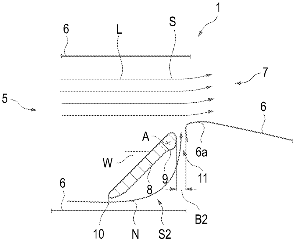
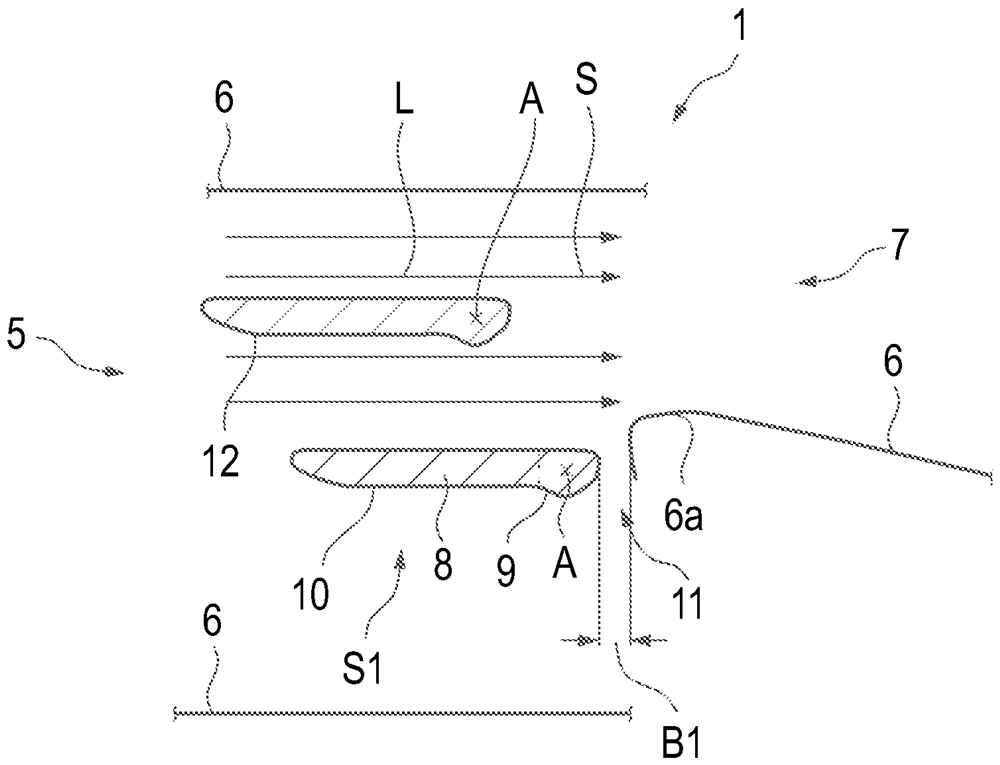
[0032] Elements with the same function and mode of action are in Figures 1 to 5 are respectively provided with the same reference numerals.

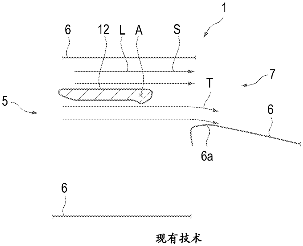
[0033] exist figure 1 A ventilation outflow device 1 according to the prior art is shown schematically in a sectional view. The ventilation outlet 1 has a ventilation channel 5 formed by a channel wall 6 with a ventilation channel outlet opening 7 . Arranged in the ventilation channel 5 are second air guide fins 12 for reversing the air flow L flowing through the ventilation channel 5 . The second air guide blade 12 is pivotally supported about the pivot axis A. The air flow L mainly flows in the horizontal flow direction S in the illustrated position of the second air guide fin 12 . In the region of the first wall section 6 a at the ventilation channel outlet opening 7 , the partial air flow T of the air flow L abuts against the channel wall 6 and is thus deflected from the remainder of the air flow L in an undesired manner.

[00...


PUM


Abstract

The invention relates to a ventilation outlet, a ventilation system and a motor vehicle, in particular to a ventilation outlet for a ventilation system of a motor vehicle for directionally blowing air into a passenger compartment of the motor vehicle with an air flow flowing in a flow direction, the ventilation outflow device has a ventilation channel for guiding the air flow therethrough, the ventilation channel having a channel wall for circumferentially delimiting the ventilation channel and a ventilation channel outlet opening for discharging the air flow into the passenger compartment; and a first air guide vane arranged in the ventilation channel for reversing the air flow, the first air guide vane having a vane head region and a vane tail region, the first air guide vane being pivotably held relative to the ventilation channel about a pivot axis between a first position and a second position, wherein the pivot axis extends through the blade head region and is arranged adjacent to the ventilation channel outlet opening.

Description

Technical field [0001] The invention relates to a ventilation outlet for a ventilation system of a motor vehicle, which ventilation outlet is used to supply the passenger compartment of the motor vehicle with directionally ventilated air with an air flow flowing in the direction of flow. Furthermore, the invention relates to a ventilation system for a motor vehicle for ventilating a passenger compartment of the motor vehicle with an air flow and to a motor vehicle having a ventilation system of this type. Background technique [0002] Ventilation systems for motor vehicles are known in which air can flow through a ventilation channel and can be deflected in a desired flow direction by means of a ventilation outlet. Many different ventilation outflow devices for ventilation systems are known, which differ in their basic principle, their tasks and their functions. For example, there are ventilation outflow devices which have rigid air guide fins via which the air flow can be ...

Claims


Application Information

Patent Timeline
Patent Type & Authority Applications(China)
IPC IPC(8): B60H1/34B60H1/26
CPCB60H1/3414B60H1/26B60H1/3421
Inventor B·赛德尔M·托马斯
Owner VOLKSWAGEN AG
Learn More