
Electromagnetic diaphragm pump

A diaphragm pump, electromagnetic technology, applied in the direction of variable capacity pump components, pumps, pump components, etc., can solve the problems of diaphragm damage, inability to shunt, not comprehensive enough, etc.

Pending Publication Date: 2022-06-24
世晃(上海)机电工业有限公司
View PDF1 Cites 0 Cited by
  • Summary
  • Abstract
  • Description
  • Claims
  • Application Information

AI Technical Summary

Problems solved by technology

[0005] In order to solve the above technical problems, the present invention provides an electromagnetic diaphragm pump to solve the problem that the existing electromagnetic diaphragm pump uses the energy storage chamber for buffering and replenishing water, which is not comprehensive enough, and at the same time, it is easy to push the diaphragm under the action of the piston rod. The diaphragm is damaged, and the single pump body setting makes it impossible to divert the water from the source, so as to buffer the water flow.

Method used


Image

  • Electromagnetic diaphragm pump
  • Electromagnetic diaphragm pump
  • Electromagnetic diaphragm pump

Examples


Embodiment

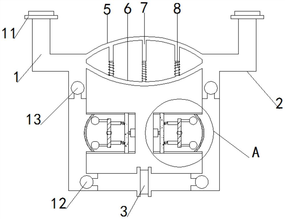
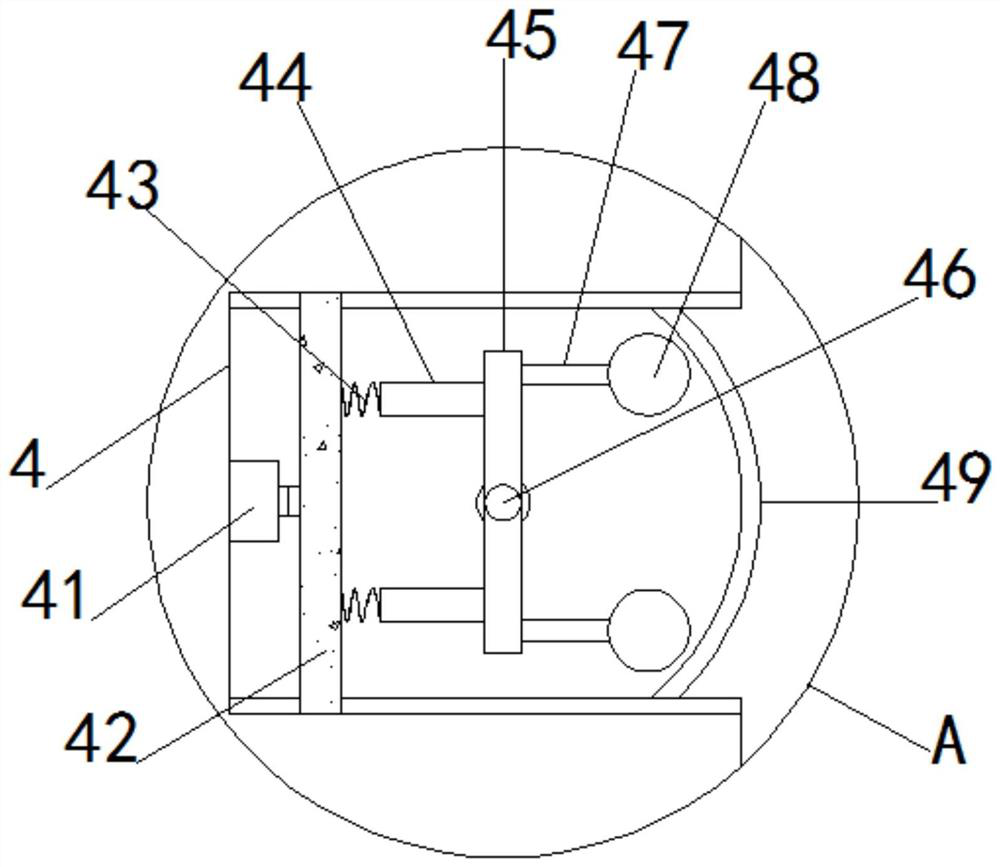
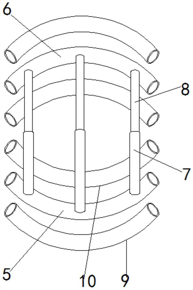
[0025] as attached figure 1 to the attached Figure 4 Shown: an electromagnetic diaphragm pump, including a left pump body 1, the lower end of the left pump body 1 is fixedly provided with a coincidence water inlet 3, and the right end of the coincidence water inlet 3 is fixedly provided with a right pump body 2, and the left pump body 1 and the An upper arc-shaped cavity 5 is arranged through the upper end of the right pump body 2, and a lower arc-shaped cavity 6 is arranged through the left pump body 1 and the right pump body 2 corresponding to the lower end of the upper arc-shaped cavity 5. The bottom of 5 is evenly provided with an upper through rod 7, and the interior of the upper through rod 7 is provided with a lower through rod 8, and the middle part of the corresponding end of the left pump body 1 and the right pump body 2 is fixedly provided with a pump cavity 4, And the corresponding end of the pump chamber 4 is installed with a micro cylinder 41, the front end of ...


PUM


Abstract

The invention provides an electromagnetic diaphragm pump, and relates to the technical field of diaphragm pumps, and the electromagnetic diaphragm pump is characterized in that micro cylinders are mounted at the corresponding ends of pump cavities, long magnets are fixedly arranged at the front ends of the micro cylinders, connecting springs are fixedly arranged at the upper and lower ends of the front sides of the long magnets, and short magnets are fixedly arranged at the other ends of the connecting springs; short magnets are fixedly arranged on the front sides of the short magnets, abutting rods are fixedly arranged on the front sides of the short magnets, abutting balls are fixedly arranged at the front ends of the abutting rods, and diaphragms are fixedly arranged on the positions, corresponding to the front ends of the abutting balls, of the pump cavity. And meanwhile, under the action of the piston rod, the diaphragm is pushed, so that the diaphragm is easily damaged, and the single pump body is arranged, so that water cannot be shunted from a source, and water flow is buffered.

Description

technical field [0001] The invention relates to the technical field of diaphragm pumps, and more particularly, to an electromagnetic diaphragm pump. Background technique [0002] The diaphragm pump is an important part of the sprayer, which is the power source of the sprayer and is used to provide the required pressure for the sprayer. [0003] Based on the above description, and search for an invention patent with application number: CN201420306465.5, which relates to an electromagnetic diaphragm pump, including a pump body and a pump cover, the pump cover is arranged on the side wall of the pump body, the pump body and the pump cover Fixed connection by bolts; a diaphragm is fixed between the pump body and the pump cover, a piston rod is arranged in the pump cover, one end of the piston rod is fixedly connected with the diaphragm through a splint, and the other end of the piston rod is fixedly connected with an armature, etc. . Through the search, it is found that it is ...

Claims


Application Information

Patent Timeline
IPC IPC(8): F04B43/04F04B53/00F04B53/10
CPCF04B43/04F04B43/0009F04B43/0081
Inventor 徐卫华
Owner 世晃(上海)机电工业有限公司
Learn More