Monitoring equipment for forest fire protection

A technology for monitoring equipment and forest fires. It is applied in the direction of mechanical equipment, cutting equipment, gardening tools/equipment, etc. It can solve problems such as stuck wind blades, difficult cleaning, and low work efficiency of staff, so as to ensure heat dissipation efficiency and prolong Endurance, the effect of improving accuracy

Inactive Publication Date: 2022-06-24
盖云 +2
View PDF0 Cites 0 Cited by
  • Summary
  • Abstract
  • Description
  • Claims
  • Application Information

AI Technical Summary

Problems solved by technology

[0003] Existing monitoring equipment for fire protection mostly convert solar energy or wind energy into electrical energy for use in order to ensure battery life. However, in forests where plants are lush and the use of solar energy is limited, most forests use wind energy into electrical energy. As the source of energy, most of the wind blades in the existing monitoring equipment for forest fire protection are only protected by the protective net, and during the long-term placement of the monitoring equipment, the surrounding trees or weeds will enter the protective net through the protective net. On the inner side, the wind blades are stuck, requiring regular cleaning by the staff, which brings a lot of inconvenience to the staff, and the weeds or trees on the inside of the protective net are intertwined, making it difficult to clean up, resulting in low work efficiency of the staff. Impact on the monitoring of forest fires

Method used


Image

  • Monitoring equipment for forest fire protection
  • Monitoring equipment for forest fire protection
  • Monitoring equipment for forest fire protection

Examples


Embodiment 1

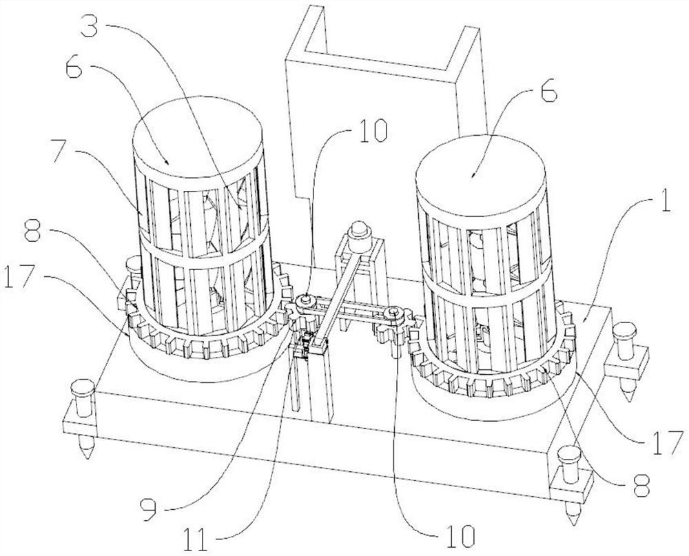
[0030] Depend on Figure 1-7 Given, the present invention includes a collection box 1, a wind shaft 2, and a wind generator 4. There are a plurality of wind shafts 2, a sleeve is installed on the wind shaft 2, and a wind blade 3 is installed on the sleeve, and the wind shaft 2 is connected to the wind power The generator 4 and the wind generator 4 are installed in the shell 5, and the outside of each wind shaft 2 is covered with a frame 6, and the frame 6 is provided with several through holes, and a cutting knife 7 is installed in the through hole, and the frame 6 The first gear 8 is installed, the first gear 8 is connected to the second gear 9, the transmission shaft 10 is interspersed in the second gear 9, and the transmission shaft 10 is connected to the cutting motor 11;

[0031] A cleaning motor 12 is installed in the casing 5, and a third gear 13 is installed on the cleaning motor 12. The third gear 13 is connected to the fourth gear 14 through tooth meshing, and the fo...

Embodiment 2

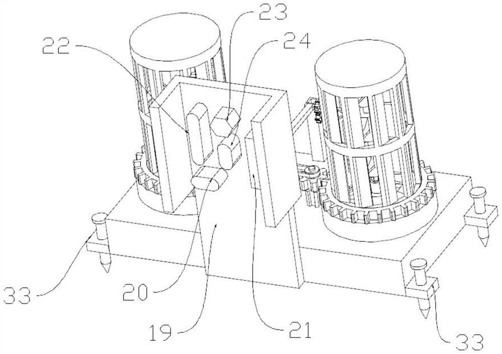
[0034] On the basis of Embodiment 1, an adjusting block 25 is installed on the collection box 1, and an adjusting plate 26 is installed in the adjusting block 25, and a camera bracket is installed on the adjusting plate 26, and a camera 27 is installed on the camera bracket, and the camera 27 has a 360 ° photography function, the collection box 1 is provided with a support frame 28 at the lowest position corresponding to the camera 27, the adjustment plate 26 can be stuck in the support frame 28, the adjustment plate 26 is connected to the rotation shaft, and the first direction adjustment gear 29 is set on the outer side of the rotation shaft , the first direction adjustment gear 29 is connected to the second direction adjustment gear 30, the second direction adjustment gear 30 is installed on the adjustment motor 31, the adjustment motor 31 is installed on the motor support 32, and the motor support 32 is installed on the collection box 1.

Embodiment 3

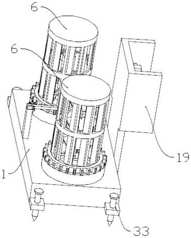
[0036] The present invention includes a collection box 1, a wind shaft 2, and a wind generator 4. There are multiple wind shafts 2, a sleeve is installed on the wind shaft 2, and a wind blade 3 is installed on the sleeve, and the wind shaft 2 is connected to the wind generator 4. , the wind generator 4 is installed in the shell 5, and the outside of each wind shaft 2 is covered with a frame 6, and the frame 6 is provided with several through holes, and a cutting knife 7 is installed in the through hole, and the frame 6 is equipped with a second A gear 8, the first gear 8 is connected to the second gear 9, the second gear 9 is interspersed with a transmission shaft 10, the transmission shaft 10 is connected to the cutting motor 11, a transmission wheel is installed on each transmission shaft 10, and a transmission belt is installed on the transmission wheel , a plurality of transmission shafts 10 are connected by transmission wheels and transmission belts; a frame 6 and a cuttin...


PUM


Abstract

The invention discloses monitoring equipment for forest fire protection, and relates to the technical field of forest fire prevention. Comprising a collecting box, a plurality of wind power shafts and a wind driven generator, sleeves are installed on the wind power shafts, wind power blades are installed on the sleeves, the wind power shafts are connected with the wind driven generator, the wind driven generator is installed in a shell, the outer side of each wind power shaft is covered with a frame, and the wind power shafts are connected with the wind driven generator. A plurality of through holes are formed in the frame, and cutting knives are installed in the through holes. According to the monitoring equipment for forest fire protection, the outer sides of the wind power shaft and the wind power blades are covered with the frame and the cutting knife, the frame is driven by the cutting motor to rotate, weeds and branches extending into the frame are cut off, the situation that the wind power blades are clamped by the weeds or the branches can be prevented, manual cleaning of workers is not needed, and the working efficiency is improved. The wind power blades can generate power normally, and the cruising ability of the device is prolonged.

Description

technical field [0001] The invention relates to the technical field of forest fire prevention, in particular to a monitoring device for forest fire protection. Background technique [0002] Forest fire prevention is a defensive measure adopted to avoid or reduce forest fire losses, and it is the fundamental measure to eliminate forest fires. Divided into two aspects of administrative measures and professional technical measures. The administrative management measures are to strengthen leadership, organize and implement the rules and regulations for forest protection and fire prevention at all levels by forest farms, and set up forest protection and fire prevention checkpoints. [0003] Existing monitoring equipment for fire protection mostly convert solar energy or wind energy into electrical energy for use in order to ensure battery life. However, in forests where plants are lush and the use of solar energy is limited, most forests use wind energy into electrical energy....

Claims


Application Information

Patent Timeline
IPC IPC(8): F16M11/04F16M11/10F16M11/18H04N5/225A01G3/08A01D34/412
CPCF16M11/046F16M11/10F16M11/18A01G3/08A01D34/412H04N23/50
Inventor 盖云张希画谭海涛金新魏玉静
Owner 盖云
Why Eureka
Try Eureka