Dual-purpose performance testing device and method for ultra-high-speed rolling bearing and gas thrust bearing

A rolling bearing and thrust bearing technology, which is applied in the field of dual-purpose performance testing devices for ultra-high-speed rolling bearings and gas thrust bearings, can solve the problems of inability to accurately simulate the running state of the bearing and errors in the evaluation and evaluation of bearing performance.

Active Publication Date: 2022-06-24
HARBIN INST OF TECH
View PDF5 Cites 0 Cited by
  • Summary
  • Abstract
  • Description
  • Claims
  • Application Information

AI Technical Summary

Problems solved by technology

[0005] The purpose of the present invention is to solve the problem that the current bearing performance simulation working condition test device using the mechanical direct contact loading method cannot accurately simulate the a

Method used


Image

  • Dual-purpose performance testing device and method for ultra-high-speed rolling bearing and gas thrust bearing
  • Dual-purpose performance testing device and method for ultra-high-speed rolling bearing and gas thrust bearing
  • Dual-purpose performance testing device and method for ultra-high-speed rolling bearing and gas thrust bearing

Examples


specific Embodiment approach 1

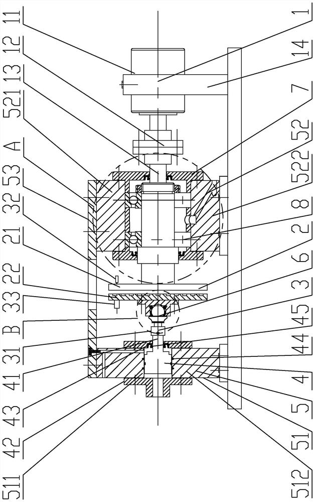
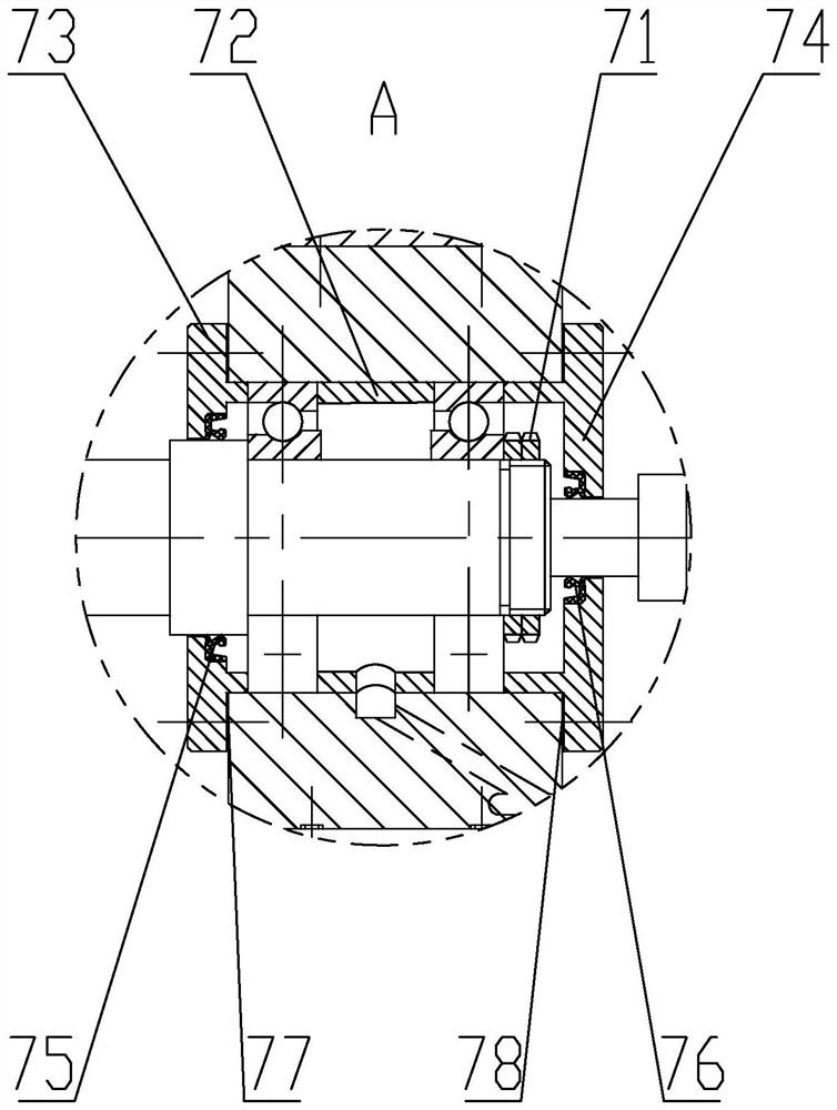
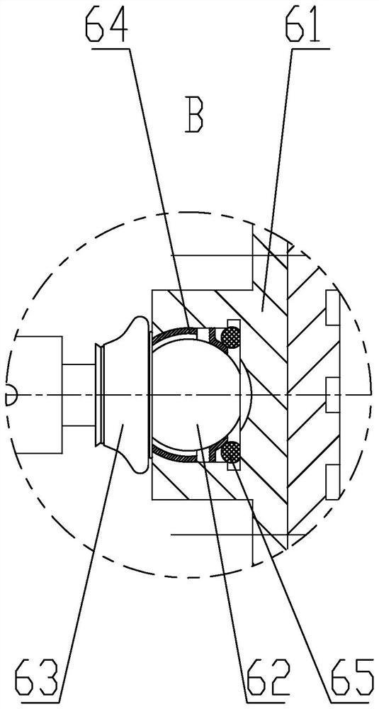
[0026] Embodiment 1: Combining Figure 1 to Figure 4 This embodiment will be described. A dual-purpose performance testing device for a super-high-speed rolling bearing and a gas thrust bearing of this embodiment includes a rotary drive structure 1 , a spiral groove gas bearing 2 , a sensor structure 3 , an axial displacement control structure 4 , and a chassis 5 , ball and socket connection structure 6, axial positioning structure 7 and ultra-high-speed rolling bearing 8, the case 5 includes a split piston support box 51 and a split rolling bearing support box 52, and the spiral groove gas bearing 2 is vertically and coaxially arranged in the split type Between the piston support box 51 and the split rolling bearing support box 52 , the spiral groove gas bearing 2 includes a rotating thrust plate 21 and a spiral groove air floating plate 22 arranged in parallel opposite to each other, and the spiral groove air floating plate 22 is close to the rotating thrust plate 21 One end...

specific Embodiment approach 2

[0031] Specific implementation mode 2: Combining figure 1 Describing this embodiment, the axial displacement control structure 4 of this embodiment further includes a felt ring 44 and a first lip seal 45 , and a sealing recess is machined on the inner wall of the piston assembly through hole of the split piston support box 51 along the circumferential direction. The felt ring 44 is embedded in the sealing groove, the plug portion of the piston rod 41 is slidably connected to the split piston support box 51 through the felt ring 44, and the inner wall of the center hole of the right end cover 43 of the hydraulic cylinder is radially machined with The first annular sealing groove, the first lip-shaped sealing ring 45 is embedded in the first annular sealing groove, and the right end cover 43 of the hydraulic cylinder is slidably and sealingly connected to the rod portion of the piston rod 41 through the first lip-shaped sealing ring 45 . In this way, in order to prevent the leak...

specific Embodiment approach 3

[0032] Specific implementation mode three: combination figure 1 Describing this embodiment, the split-type piston support box 51 of this embodiment includes an upper piston support box 511 and a lower piston support box 512 , the upper piston support box 511 is fixed on the lower piston support box 512 by screws, and the upper piston support box 511 is fixed on the lower piston support box 512 by screws. The support box 511 is internally processed with a first oil circuit that communicates with the rod cavity of the hydraulic cylinder, and the other end of the first oil circuit is connected to an external oil tank and an oil pump through an oil delivery pipe; the split rolling bearing support box 52 includes an upper rolling bearing support box 521 and the lower rolling bearing support box 522, the upper rolling bearing support box 521 is fixed on the lower rolling bearing support box 522 by screws, and the lower rolling bearing support box 522 is internally machined with a sec...


PUM


Abstract

The invention discloses a dual-purpose performance testing device and method for an ultra-high-speed rolling bearing and a gas thrust bearing, and relates to the technical field of bearing testing. The bearing performance simulation working condition test device solves the problem that an error occurs in bearing performance assessment and evaluation due to the fact that an existing bearing performance simulation working condition test device adopting a mechanical direct contact loading mode cannot accurately simulate the actual operation state of a bearing. A high-speed driver is connected with one end of a shaft, the other end of the shaft penetrates through a rolling bearing assembling through hole and is connected with a rotating thrust plate, an ultra-high-speed rolling bearing located in the rolling bearing assembling through hole is sequentially arranged on the shaft from right to left, and a piston rod penetrates through a right end cover of a hydraulic cylinder and is connected with a spiral groove air floating disc through a ball socket connecting structure. The load sensor is installed between the piston rod and the ball socket connecting structure, the laser transmitter is installed on the rotating thrust plate, and the laser vibration sensor is installed on the spiral groove air floating disc. The device and the method are used for simultaneously carrying out simulation working condition test on the ultra-high-speed performance of the rolling bearing and the gas thrust bearing.

Description

technical field [0001] The invention relates to the technical field of bearing testing, in particular to a dual-purpose performance testing device and method for an ultra-high-speed rolling bearing and a gas thrust bearing. Background technique [0002] In the power transmission system of high-speed mechanical equipment, rolling bearings and gas thrust bearings are two typical key basic components, and their running accuracy and stability play a decisive role in the life and reliability of ultra-high-speed mechanical equipment. Especially with the increasing speed of high-end equipment in aerospace, rail transit and other fields, even reaching more than 100,000 r / min, once the ultra-high-speed rolling bearing or gas thrust bearing used in its power transmission system fails, it will cause catastrophic consequences to the mechanical system. . Therefore, it is particularly necessary to evaluate and test the performance of ultra-high-speed rolling bearings and gas thrust beari...

Claims


Application Information

Patent Timeline
IPC IPC(8): G01M13/04
CPCG01M13/04
Inventor 张传伟翟晗古乐王黎钦郑德志赵小力
Owner HARBIN INST OF TECH
Why Eureka
Try Eureka