
Automobile A column side column collision test device

A test device and automobile technology, applied in the direction of measuring device, using one-time impact force test material strength, impact test, etc., can solve the long preparation period, increase the development cycle, and it is difficult to accurately reflect the deformation of the vehicle's side column impact and side wall and other problems, to achieve the effect of reducing test cost, ensuring test accuracy, convenient deformation and bending resistance

Pending Publication Date: 2022-06-28
LINGYUN INDAL CORP
View PDF0 Cites 0 Cited by
  • Summary
  • Abstract
  • Description
  • Claims
  • Application Information

AI Technical Summary

Problems solved by technology

[0005] 1) The side column impact test of the whole vehicle is mainly used to verify the structural strength of the whole body, the damage of the dummy and the restraint system, etc., but the test cost of the whole vehicle is high and the preparation period is long, so it is not suitable for multiple rounds of verification of the side body and side wall structure. verification, greatly increasing the development cycle
[0006] 2) Although the test method of side pillar impact of subsystems or parts can greatly reduce the test cost and shorten the preparation period, it is difficult to accurately reflect the deformation of the side pillar impact of the vehicle
The side column impact test method of the subsystem requires a large number of environmental parts, almost involving the entire side wall, requiring matching of various parts, and the processing cost is also high
However, the parts experiment lacks enough environmental parts, so it can only reflect its own bending or crushing deformation ability, and the accuracy is very poor.

Method used


Image

  • Automobile A column side column collision test device
  • Automobile A column side column collision test device
  • Automobile A column side column collision test device

Examples


Embodiment Construction

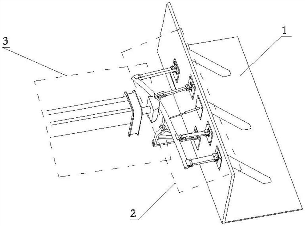
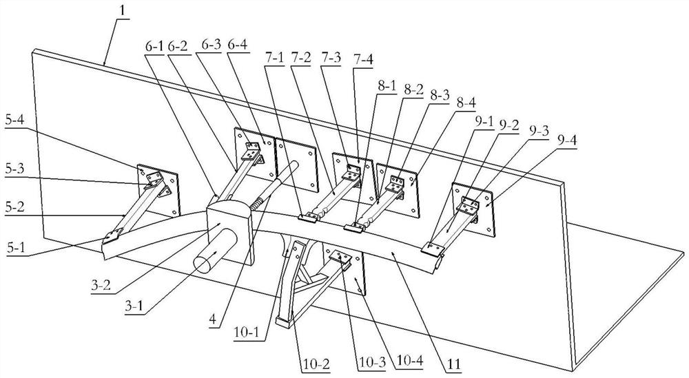
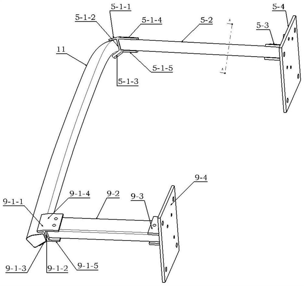
[0037] refer to Figure 1-2 , an automobile A-pillar side column impact test device, comprising impact equipment 3, A-pillar holding tooling 2 and test installation fixing bench 1; A-pillar holding tooling 2 is connected with the test installation fixing bench 1, A-pillar 11 passes through A The column support tool 2 is connected to the test installation and fixed bench 1. The test installation and fixed bench 1 is fixed on the ground or a flat table. The impact equipment 3 is connected with a pneumatic or motor traction device, and the impact equipment 3 drives the impact head through pneumatic or motor traction. The A-pillar 11 is hit at a certain speed, and the impact position is the contact position of the side column of the vehicle. The impact device 3 includes an impact head 3-2. The rear end of the impact head 3-2 is provided with a sensor 3-1, and the rear of the A-pillar 11 is provided with a Displacement sensor 4, the other end of the displacement sensor 4 is connect...


PUM


Abstract

The invention relates to an automobile A column side column collision test device which comprises impact equipment, an A column clamping tool and a test installation fixing rack, the A column clamping tool is connected with the test installation fixing rack, an A column is connected with the test installation fixing rack through the A column clamping tool, the test installation fixing rack is fixed to the ground or a flat table top, and the impact equipment is connected with the A column clamping tool. The impact equipment is connected with a pneumatic or motor traction device and comprises an impact head, a force value sensor is arranged at the rear end of the impact head, a displacement sensor is arranged behind the A column, and the other end of the displacement sensor is connected with the test installation fixing rack. According to the invention, by matching the deformation mode of the environmental part around the A column, the replacement of the environmental part with a simplified structure is realized, the test cost is greatly reduced while the test precision is ensured as far as possible, and the deformation and bending resistance of the A column when the side column is collided becomes possible to be economically and conveniently measured.

Description

technical field [0001] The invention relates to an automobile A-pillar side pillar impact test device. Background technique [0002] Since the buffer space is much smaller in a side collision than in a frontal collision, the occupants are more likely to be seriously injured in a side collision. In order to promote automobile manufacturers to improve the side protection technology of automobiles, various countries have put forward strict requirements on side collision regulations in government regulations, NCAP and insurance association regulations. Side collision regulations include movable obstacle avoidance side collision (MDB) and side column collision (POLE) regulations. The side column collision regulations mainly examine the situation where the car runs out of control and hits a utility pole or a tree on the side, which is likely to cause more serious damage to the occupants. In view of the side pillar collision regulations, more stringent requirements are put forward...

Claims


Application Information

Patent Timeline
IPC IPC(8): G01M7/08G01N3/06G01N3/30G01B21/32
CPCG01M7/08G01N3/06G01N3/30G01B21/32G01N2203/001G01N2203/06G01N2203/0682G01N2203/0266
Inventor 李月吴文珍耿晓勇李彦波孟宪瑞杨香玉王惠
Owner LINGYUN INDAL CORP
Learn More