Optical lens
An optical lens and lens technology, applied in the field of optical lenses, can solve the problems of low imaging quality, small field of view, low definition, etc., and achieve the effect of high imaging quality, large field of view, and high definition
- Summary
- Abstract
- Description
- Claims
- Application Information
AI Technical Summary
Problems solved by technology
Method used
Image

Examples
Embodiment 1
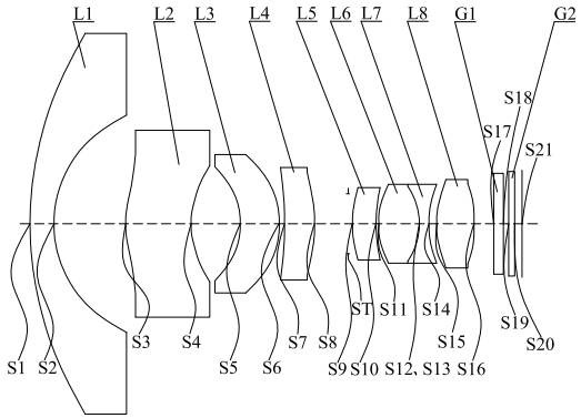
[0124] see figure 1 , which is a schematic structural diagram of the optical lens provided in Embodiment 1 of the present invention. The optical lens sequentially includes from the object side to the imaging plane along the optical axis: a first lens L1, a second lens L2, a third lens L3, a fourth lens Lens L4, diaphragm ST, fifth lens L5, sixth lens L6, seventh lens L7, eighth lens L8, filter G1 and protective glass G2.
[0125] The first lens L1 has negative refractive power, the object side S1 is convex, and the image side S2 is concave;
[0126] The second lens L2 has negative refractive power, the object side S3 is convex, and the image side S4 is concave;
[0127] The third lens L3 has positive refractive power, the object side S5 is concave, and the image side S6 is convex;
[0128] The fourth lens L4 has positive refractive power, the object side S7 is concave, and the image side S8 is convex;
[0129] aperture ST;
[0130] The fifth lens L5 has positive refractive...
Embodiment 2
[0152] see Figure 8 , which is a schematic diagram of the structure of the optical lens provided in Embodiment 2 of the present invention. The optical lens sequentially includes from the object side to the imaging plane along the optical axis: a first lens L1, a second lens L2, a third lens L3, a fourth lens Lens L4, diaphragm ST, fifth lens L5, sixth lens L6, seventh lens L7, eighth lens L8, filter G1 and protective glass G2.
[0153] The first lens L1 has negative refractive power, the object side S1 is convex, and the image side S2 is concave;
[0154] The second lens L2 has negative refractive power, the object side S3 is convex, and the image side S4 is concave;
[0155] The third lens L3 has positive refractive power, the object side S5 is concave, and the image side S6 is convex;
[0156] The fourth lens L4 has positive refractive power, the object side S7 is concave, and the image side S8 is convex;
[0157] aperture ST;
[0158] The fifth lens L5 has a positive r...
Embodiment 3
[0177] see Figure 15 , which is a schematic structural diagram of the optical lens provided in Embodiment 3 of the present invention. The optical lens includes a first lens L1, a second lens L2, a third lens L3, a fourth lens L1, a second lens L2, a fourth lens L3, and a fourth lens along the optical axis from the object side to the imaging plane. Lens L4, diaphragm ST, fifth lens L5, sixth lens L6, seventh lens L7, eighth lens L8, filter G1 and protective glass G2.
[0178] The first lens L1 has negative refractive power, the object side S1 is convex, and the image side S2 is concave;
[0179] The second lens L2 has negative refractive power, the object side S3 is convex, and the image side S4 is concave;
[0180] The third lens L3 has positive refractive power, the object side S5 is concave, and the image side S6 is convex;
[0181] The fourth lens L4 has positive refractive power, the object side S7 is convex, and the image side S8 is concave;
[0182] aperture ST;
[...
PUM
 Abstract
Description
Claims
Application Information
 - R&D Engineer
- R&D Manager
- IP Professional
- Industry Leading Data Capabilities
- Powerful AI technology
- Patent DNA Extraction
Browse by: Latest US Patents, China's latest patents, Technical Efficacy Thesaurus, Application Domain, Technology Topic.
© 2024 PatSnap. All rights reserved.Legal|Privacy policy|Modern Slavery Act Transparency Statement|Sitemap