Tillage part performance test bench for improving degraded grassland
A technology of degraded grassland and test bench, applied in the field of testing and experimentation, can solve the problems such as the inability of the tillage parts to be in good contact with the soil, the inability to achieve accurate testing of the tillage parts, and the existence of the soil when the tillage parts are separated, so as to ensure the accuracy and practicability of the test. High and wide range of effects
- Summary
- Abstract
- Description
- Claims
- Application Information
AI Technical Summary
Problems solved by technology
Method used
Image
Examples
Embodiment 1
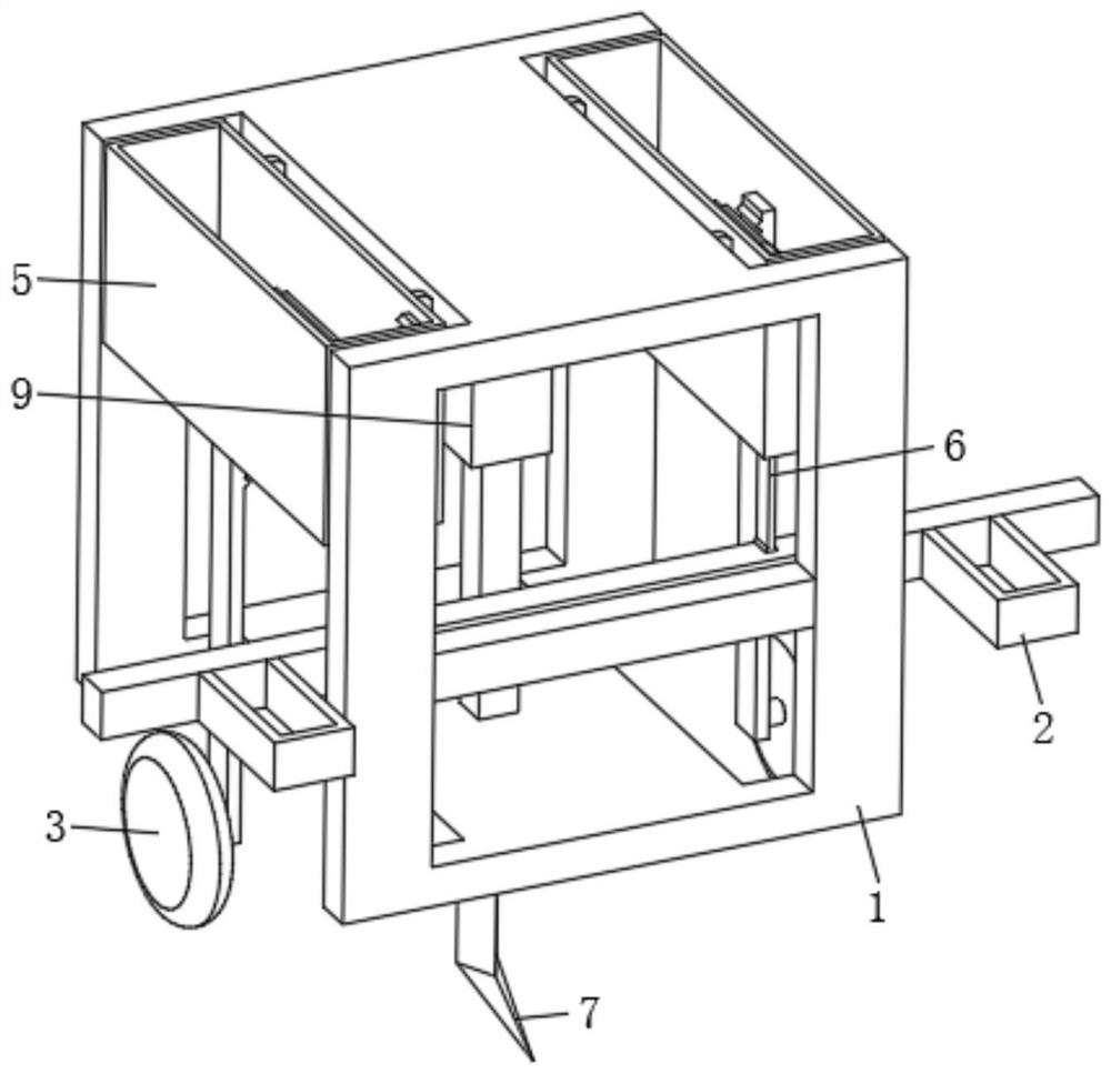
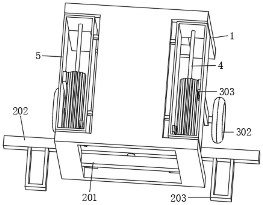
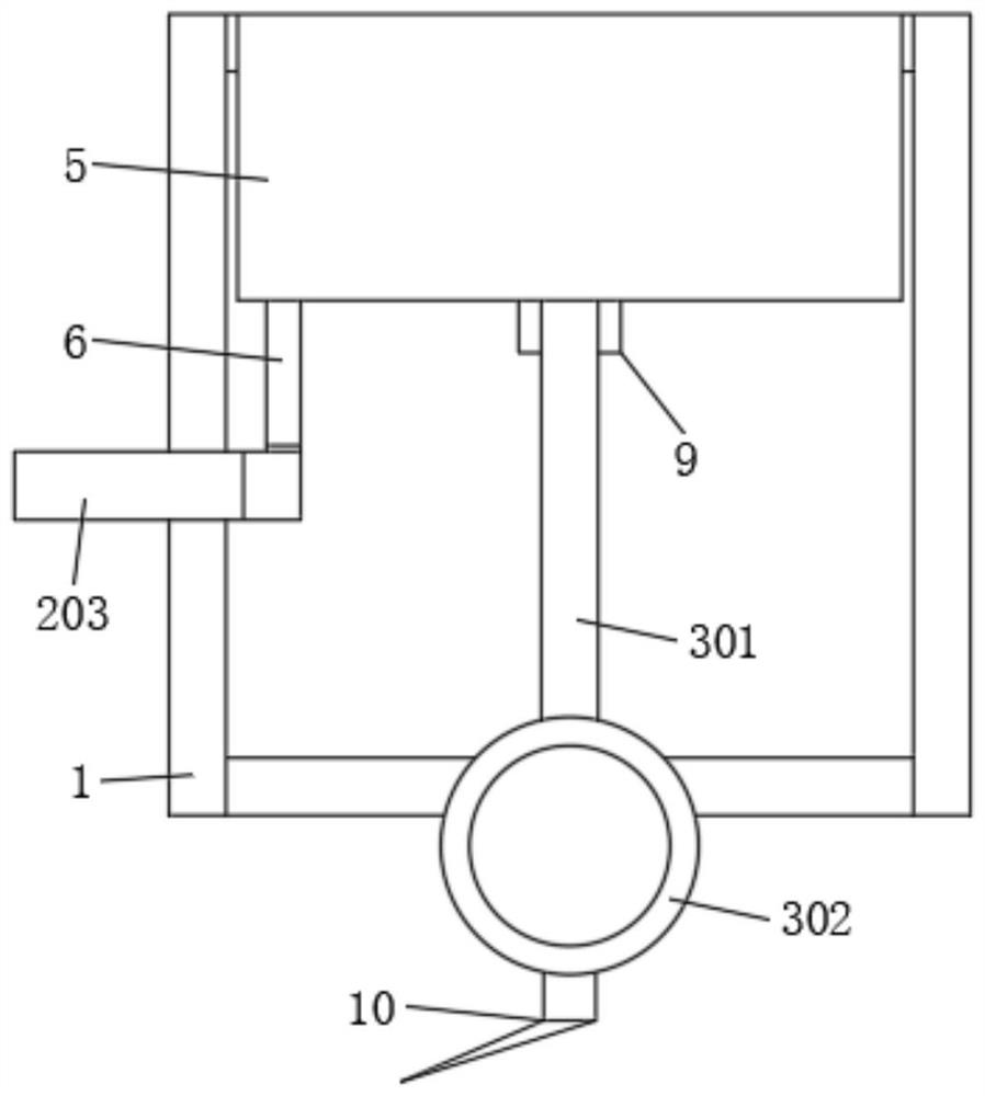
[0033] see Figure 1 to Figure 6 , an embodiment of the present invention provides a performance test bench for a tillage component 7 for improving degraded grassland: including a frame 1, a tillage component 7 and a data acquisition device arranged on the tillage component 7, the data acquisition device can The data analysis work is carried out by exporting to the PC through the U disk; the left and right sides of the frame 1 are rotated and installed with the casing 5, and the casing 5 is designed to be penetrated up and down. The interior of the frame 1 is slidably installed with a moving assembly 3 that is connected to the rotating assembly 4. The moving assembly 3 can slide up and down along the inner wall of the casing 5, and the synchronous movement of the casing 5 can be realized through the moving assembly 3; the interior of the frame 1 is fixedly installed with Control assembly 2, the control assembly 2 can be detachably connected with an external driving device (suc...
Embodiment 2
[0043] see Figure 1 to Figure 8 , on the basis of the first embodiment, the connecting rod 401 includes a round rod and a key rod that are fixedly connected, the round rod and the key rod are both rotatably connected with the inner wall of the housing 5, and the tooth column 402 is fixedly installed on the outer surface of the round rod, The tooth column 402 and the round rod are the same as those in the first embodiment.
[0044] The adjustment assembly 6 includes a third rack 6001 rotatably connected to the long rod 202 and engaged with the gear column 402 and a second block 6002 slidably sleeved on the outer surface of the key rod. The third rack 6001 and the second rack 601 It is exactly the same, the shape of the first clamping block 602 and the second clamping block 6002 are also the same, but the second clamping block 6002 is assembled with the key rod in a key shaft type, that is, the second clamping block 6002 can rotate with the key rod and can also be relative to t...
Embodiment 3
[0048] see Figure 1 to Figure 10 , on the basis of the second embodiment, the moving assembly 3 includes a second side plate 3001 , a second roller 3002 is rotatably installed under the second side plate 3001 , the second side plate 3001 and the second roller 3002 are connected with the first side plate 301 It is exactly the same as the first roller 302; the top of the second side plate 3001 is fixedly installed with a double-sided rack 3003, and the double-sided rack 3003 and the rear surface of the second side plate 3001 are fixed and installed together with the inner wall of the casing 5. The dovetail bar 3004 is provided on the inner wall of the housing 5 with a dovetail slot 8 for the dovetail bar 3004 to slide up and down. In this embodiment, the inner wall of the housing 5 does not need to have a chute, and the double-sided rack 3003 does not need to be in contact with the inner wall of the housing 5. Meanwhile, the third rack 6001 can be located on the opposite side o...
PUM
 Abstract
Description
Claims
Application Information
 - R&D
- Intellectual Property
- Life Sciences
- Materials
- Tech Scout
- Unparalleled Data Quality
- Higher Quality Content
- 60% Fewer Hallucinations
Browse by: Latest US Patents, China's latest patents, Technical Efficacy Thesaurus, Application Domain, Technology Topic, Popular Technical Reports.
© 2025 PatSnap. All rights reserved.Legal|Privacy policy|Modern Slavery Act Transparency Statement|Sitemap|About US| Contact US: help@patsnap.com


