Self-sinking type seabed earthquake acquisition device and method thereof

A collection device, self-sinking technology, applied in circuit devices, battery circuit devices, seismology for areas covered by water, etc., can solve problems such as time limit for marine seismographs to work

Active Publication Date: 2022-07-01
THE FIRST INST OF OCEANOGRAPHY SOA
12 Cites 0 Cited by

AI-Extracted Technical Summary

Problems solved by technology

[0002] When the marine seismograph works on the seabed, the battery is used to provide the energy required for the...

Method used

As shown in Fig. 1-Fig. 4, in the embodiment of the present invention, the first propulsion device 5 comprises the first propeller 51, the second propeller 52, the third propeller 53 and the fourth propeller 54, the first The propeller 51, the second propeller 52, the third propeller 53 and the fourth propeller 54 are arranged around the base 1 respectively, the first propeller 51, the second propeller 52, the third propeller 53 and the fourth propeller The water flow input end and the water flow output end of the device 54 are parallel to the top of the base 1, and the first controller 32 controls the first propeller 51, the second propeller 52, and the third propeller according to the data detected by the first tilt sensor 33. 53 and the fourth thruster 54 start, shut down, rotate forward or reverse to adjust the attitude of the seabed seismograph 3 in com...

Abstract

The invention discloses a self-sinking type seabed earthquake acquisition device and method, and relates to the technical field of seabed earthquake data acquisition, and the self-sinking type seabed earthquake acquisition device comprises a base, a counterweight, a seabed seismograph, a first underwater acoustic transducer, a first propulsion device, a first electric energy exchange device, an energy conversion device and an energy storage device. The solar cell panel converts light energy into electric energy for storage, and the electric energy stored by the energy storage device is obtained through the transduction device and then is supplemented to the ocean bottom seismograph, so that the ocean bottom seismograph can work on the sea for a long time.

Application Domain

Circuit monitoring/indicationElectric power +3

Technology Topic

Ocean bottom seismographSolar battery +12

Image

  • Self-sinking type seabed earthquake acquisition device and method thereof
  • Self-sinking type seabed earthquake acquisition device and method thereof
  • Self-sinking type seabed earthquake acquisition device and method thereof

Examples

  • Experimental program(1)

Example Embodiment

[0044] Exemplary embodiments of the present disclosure will be described in more detail below with reference to the accompanying drawings. While exemplary embodiments of the present disclosure are shown in the drawings, it should be understood that the present disclosure may be embodied in various forms and should not be limited by the embodiments set forth herein. Rather, these embodiments are provided so that the present disclosure will be more thoroughly understood, and will fully convey the scope of the present disclosure to those skilled in the art.
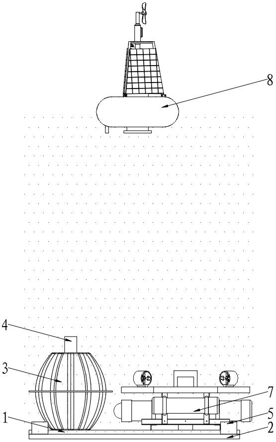
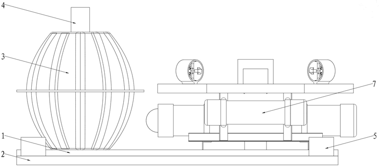
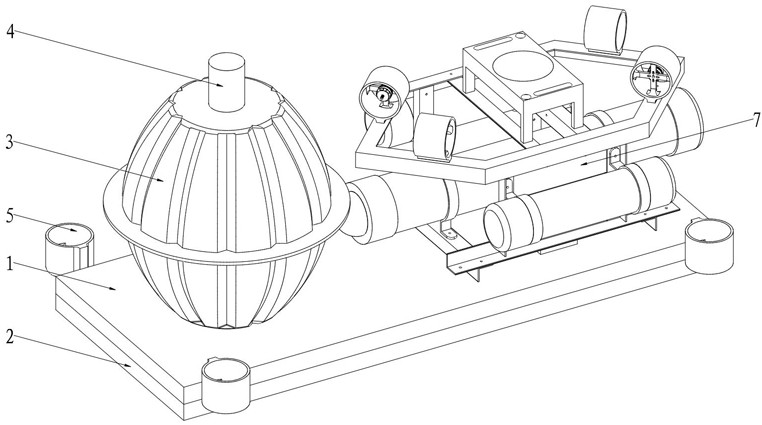
[0045] like Figure 1-Figure 12As shown, the embodiment of the present invention provides a self-sinking submarine seismic acquisition device, which includes a base 1, a counterweight 2 is arranged at the bottom of the base 1, a submarine seismometer 3 is arranged on one side of the top of the base 1, and the top of the base 1 is on the other side. A first power exchange device 6 is provided on one side, and a first power source 31, a first controller 32 and a first tilt sensor 33 are arranged inside the seabed seismograph 3, and the first power source 31 is used to provide the work of the seabed seismograph 3 required. The top of the submarine seismograph 3 is provided with a first underwater acoustic transducer 4, and around the base 1 is provided with a first propulsion device 5, and the first controller 32 is respectively connected with the first propulsion device 5 and the first underwater acoustic exchange The energy converter 4 is connected in communication with the first electric energy exchange device 6, and the energy exchange device 7 includes a frame body 71, a main cabin body 72, an auxiliary cabin body 73, a second propulsion device 74, a second electric energy exchange device 75, and a third electric energy exchange device. 76. The first fixing seat 77 and the second fixing seat 78, the frame body 71 is arranged on the other side of the top of the base 1, the main cabin body 72 is arranged laterally on the inner side of the frame body 71, and the auxiliary cabin body 73 is arranged laterally on the frame body On the other side inside the body 71, the second propulsion device 74 is arranged around the top of the frame body 71, the first fixing seat 77 is longitudinally arranged in the middle of the bottom of the frame body 71, and the second fixing seat 78 is longitudinally arranged on the frame body In the middle of the top of 71 , the second power exchange device 75 is arranged on the first fixed seat 77 , the third power exchange device 76 is arranged on the second fixed seat 78 , and the second power exchange device 75 communicates with the first power exchange device 6 . The main cabin 72 is connected to the first underwater acoustic transducer 4 in communication, and the energy storage device 8 includes a floating platform 81, a fixed frame 82, a solar panel 83, a second drive motor 84, a ninth thruster 85, and a casing. 86. The third controller 87, the charge and discharge management module 88, the third power supply 89, the fourth power exchange device 810, the tenth underwater acoustic transducer 811 and the positioning module 812, the fixing frame 82 is arranged on the top of the floating platform 81, The solar panel 83 is arranged on the periphery of the fixing frame 82, the second driving motor 84 is arranged on the top of the fixing frame 82, one side of the ninth propeller 85 is connected with one side of the output shaft of the second driving motor 84, and the casing 86 is arranged Inside the floating platform 81 , and the casing 86 partially extends to the outside of the floating platform 81 . At the bottom, the third controller 87 , the charge and discharge management module 88 , the positioning module 812 and the third power source 89 are sequentially arranged inside the casing 86 , the tenth underwater acoustic transducer 811 is communicatively connected with the main cabin 72 , and the fourth power The exchange device 810 is connected in communication with the third electric energy exchange device 76, and the positioning module 812 is in communication connection with the third controller 87. By adding the energy conversion device 7 and the energy storage device 8, the solar panel 83 converts light energy into electric energy for storage, At the same time, the electric energy stored in the energy storage device 8 is obtained through the transducer device 7 and then supplemented to the seabed seismograph 3, so as to achieve the effect of making the marine seismograph work on the seabed for a long time.
[0046] It should be noted that the counterweight 2 is used for the self-sinking submarine seismic acquisition device to offset its own buoyancy, so as to facilitate sinking to the seabed. The material of the counterweight 2 can be metal or other materials, and it is connected to the submarine seismograph 3. The specific connection structure It is the prior art, so its specific structure, connection manner and working principle will not be described again.
[0047] like Figure 1-Figure 4 As shown, in the embodiment of the present invention, the first propeller 5 includes a first propeller 51 , a second propeller 52 , a third propeller 53 and a fourth propeller 54 . The first propeller 51 and the second propeller 52 , The third propeller 53 and the fourth propeller 54 are respectively arranged around the base 1, the water flow input end and the water flow output of the first propeller 51, the second propeller 52, the third propeller 53 and the fourth propeller 54 The end is parallel to the top of the base 1. The first controller 32 controls the activation of the first thruster 51, the second thruster 52, the third thruster 53 and the fourth thruster 54 according to the data detected by the first tilt sensor 33. , turn off, turn forward or reverse to adjust the posture of the seabed seismograph 3 in combination with the data detected by the first tilt sensor 33, so that the seabed seismograph 3 can keep the upward posture of the seabed seismograph 3 and sink into the seabed smoothly, which is convenient for subsequent work.
[0048] like Figure 4 As shown, in the embodiment of the present invention, the first power exchange device 6 includes a first positioning device 61 and a first wireless charging and discharging module 62, and the first positioning device 61 includes a second underwater acoustic transducer 611, a first electromagnet 612 , the third underwater acoustic transducer 613 and the second electromagnet 614, the first electromagnet 612 and the second underwater acoustic transducer 611 are arranged laterally on the other side of the top of the base 1, and the first wireless charging and discharging module 62 is arranged at The other side of the top of the base 1 is located below the first electromagnet 612 and the second underwater acoustic transducer 611, the third underwater acoustic transducer 613 and the second electromagnet 614 are laterally arranged on the other side of the top of the base 1, Located below the first wireless charging and discharging module 62, the signal output end of the first controller 32 is connected to the first propeller 51, the second propeller 52, the third propeller 53, the fourth propeller 54, the first propeller 54, the first propeller 54, and the first propeller respectively. The signal input terminals of the transducer 4, the second underwater acoustic transducer 611, the third underwater acoustic transducer 613, the first electromagnet 612 and the second electromagnet 614 are connected in communication, and the signal input terminal of the first controller 32 They are respectively connected in communication with the signal output terminals of the first underwater acoustic transducer 4 , the second underwater acoustic transducer 611 , the third underwater acoustic transducer 613 , and the first tilt sensor 33 , and the power supply of the first wireless charging and discharging module 62 The output terminal is connected in communication with the power input terminal of the first power source 31 . The first power exchange device 6 is used for detecting and supplementing the power stored in the first power source 31 , and is also used for attracting the first magnet 7512 through the first electromagnet 612 . The electromagnet 614 attracts the second magnet 7514 to adjust the position of the transducer device 7 so that the second wireless charging and discharging module 752 is aligned with the first wireless charging and discharging module 62 .
[0049] like Figure 1-Figure 3 , Figure 5-Figure 6 and Figure 11 As shown, in the embodiment of the present invention, an eleventh underwater acoustic transducer 721 is provided on one side of the main cabin 72 for receiving and sending signals to the first underwater acoustic transducer 4 and the tenth underwater acoustic transducer The interior of the main cabin 72 is sequentially provided with a second controller 722, a second power supply 723, a second tilt sensor 79, an air bag 724 and a trachea 725, and the eleventh underwater acoustic transducer 721 is respectively connected with the first underwater acoustic transducer 721. The transducer 4 is connected in communication with the tenth hydroacoustic transducer 811, the eleventh hydroacoustic transducer 721 and the second tilt sensor 79 are connected in communication with the second controller 722, one end of the trachea 725 is communicated with the air bag 724, and the trachea The other end of 725 is communicated with the auxiliary cabin 73 .
[0050] Specifically, the second inclination sensor 79 is used to detect the posture of the transducer device 7. During the process of the transducer device 7 approaching the energy storage device 8 and the first power exchange device 6, the data detected by the second inclination sensor 79, the first The second controller 722 controls the second propulsion device 74 to adjust the attitude of the transducer device 7 , so that the transducer device 7 can better connect with the energy storage device 8 and the first power exchange device 6 .
[0051] like Figure 1-Figure 3 , Figure 5-Figure 6 and Figure 10 As shown, in the embodiment of the present invention, a first pontoon 731, a first drive motor 733 and a second pontoon 732 are arranged in the interior of the auxiliary cabin 73 in sequence, and a first threaded hole 7311 is provided at the axis of the first pontoon 731, A second threaded hole 7321 is provided at the shaft center of the second buoy 732, the output end of the first driving motor 733 is connected with a first screw 734 and a second screw 735, respectively, the first screw 734 and the first buoy 731 pass through the first screw The hole 7311 is threadedly connected, the second screw 735 is simultaneously connected with the second buoy 732 through the second screw hole 7321, the screw thread direction of the first screw 734 and the second screw 735 are opposite, and the first screw hole 7311 and the second screw hole 7321 are Blind holes, the interiors of the first pontoon 731 and the second pontoon 732 are hollow, and the signal input end of the first drive motor 733 is communicatively connected to the signal output end of the second controller 722 .
[0052] Specifically, when the transducer device 7 rises, the second controller 722 activates the first drive motor 733, and the first drive motor 733 drives the first pontoon 731 and the second pontoon 732 from the auxiliary via the first screw 734 and the second screw 735. The cabin 73 protrudes, and the auxiliary cabin 73 sucks the air inside the airbag 724 into the auxiliary cabin 73 through the trachea 725. At this time, the buoyancy of the transducer device 7 is greater than the gravity, and the transducer device 7 floats up. When descending, the second controller 722 starts the first drive motor 733, and the first drive motor 733 drives the first pontoon 731 and the second pontoon 732 to retract into the auxiliary cabin 73 through the first screw 734 and the second screw 735, and the auxiliary cabin The air inside the body 73 stores the air inside the airbag 724 through the trachea 725. At this time, the buoyancy of the transducer device 7 is smaller than the gravity, and the transducer device 7 sinks.
[0053] like Figure 1-3 As shown in and 5-6, in the embodiment of the present invention, the second propeller 74 includes a fifth propeller 741, a sixth propeller 742, a seventh propeller 743, and an eighth propeller 744. The sixth propeller 742, the seventh propeller 743 and the eighth propeller 744 are respectively arranged around the top of the frame body 71, and the fifth propeller 741, the sixth propeller 742, the seventh propeller 743 and the eighth propeller 744 The signal input terminals are respectively connected in communication with the signal output terminals of the second controller 722 .
[0054] Specifically, according to the data detected by the second tilt sensor 79, the second controller 722 respectively controls the fifth propeller 741, the sixth propeller 742, the seventh propeller 743 and the eighth propeller 744 to start, close, rotate forward or The attitude of the transducer device 7 is adjusted by reversing and combined with the data detected by the second tilt sensor 79 , so that the transducer device 7 can better connect with the energy storage device 8 and the first power exchange device 6 .
[0055] like figure 1 , figure 2 and Image 6 As shown, in the embodiment of the present invention, the second power exchange device 75 includes a second positioning device 751 and a second wireless charging and discharging module, and the second positioning device 751 includes a fourth underwater acoustic transducer 7511, a first magnet 7512, a second The five underwater acoustic transducers 7513 and the second magnet 7514 , the first magnet 7512 and the fourth underwater acoustic transducer 7511 are laterally arranged on the bottom of the first fixing seat 77 , and the second wireless charging and discharging module is arranged on the first fixing seat 77 The bottom is located on one side of the first magnet 7512 and the fourth underwater acoustic transducer 7511, and the fifth underwater acoustic transducer 7513 and the second magnet 7514 are laterally arranged on the bottom of the first fixing seat 77 and located on the second wireless charging and discharging module. On one side of 752 , the fourth underwater acoustic transducer 7511 is in communication connection with the second underwater acoustic transducer 611 , and the fifth underwater acoustic transducer 7513 is in communication connection with the third underwater acoustic transducer 613 .
[0056] like Figure 1-Figure 3 and Figure 5As shown, in the embodiment of the present invention, the third power exchange device 76 includes a third positioning device 761 and a third wireless charging and discharging module 762, and the third positioning device 761 includes a sixth underwater acoustic transducer 7611, a third magnet 7612, The seventh underwater acoustic transducer 7613 and the fourth magnet 7614, the third magnet 7612 and the sixth underwater acoustic transducer 7611 are arranged laterally on the top of the second fixing seat 78, and the third wireless charging and discharging module 762 is arranged on the second fixing seat The top of the seat 78 is located on one side of the third magnet 7612 and the sixth underwater acoustic transducer 7611, and the seventh underwater acoustic transducer 7613 and the fourth magnet 7614 are laterally arranged on the top of the second fixed seat 78 and located on the third wireless charger. On one side of the discharge module 762, the signal output end of the second controller 722 is connected to the fifth propeller 741, the sixth propeller 742, the seventh propeller 743, the eighth propeller 744, and the fourth hydroacoustic transducer 7511 respectively. , the fifth underwater acoustic transducer 7513, the sixth underwater acoustic transducer 7611, the seventh underwater acoustic transducer 7613, the eleventh underwater acoustic transducer 721, the second wireless charging and discharging module and the third wireless charging and discharging module The signal input end of the module 762 is communicatively connected, and the signal input end of the second controller 722 is respectively connected with the fourth underwater acoustic transducer 7511, the fifth underwater acoustic transducer 7513, the sixth underwater acoustic transducer 7611, the seventh underwater acoustic transducer The signal output terminals of the acoustic transducer 7613 and the eleventh underwater acoustic transducer 721 are communicatively connected, the power output terminal of the second wireless charging and discharging module 752 is connected to the power input terminal of the first wireless charging and discharging module 62, and the second power source The output end of 723 is connected to the input end of the second wireless charging and discharging module 752 , and the input end of the second power supply 723 is connected to the power output end of the third wireless charging and discharging module 762 .
[0057] like Figure 7-Figure 9 As shown, in the embodiment of the present invention, the fourth power exchange device 810 includes a fourth positioning device 8101 and a fourth wireless charging and discharging module 8102, and the fourth positioning device 8101 includes an eighth underwater acoustic transducer 81011, a third electromagnet 81012 , the ninth underwater acoustic transducer 81013 and the fourth electromagnet 81014, the third electromagnet 81012 and the eighth underwater acoustic transducer 81011 are arranged horizontally at the bottom of the casing 86, and the fourth wireless charging and discharging module 8102 is arranged on the casing The bottom of 86 is located on one side of the third electromagnet 81012 and the eighth underwater acoustic transducer 81011, the ninth underwater acoustic transducer 81013 and the fourth electromagnet 81014 are laterally arranged on the bottom of the casing 86 and located at the fourth wireless charging and discharging On one side of the module 8102, the signal output end of the third controller 87 is connected to the ninth thruster 85, the second drive motor 84, the third electromagnet 81012, the fourth electromagnet 81014, the charge and discharge management module 88, the fourth wireless The signal input terminals of the charging and discharging module 8102, the eighth underwater acoustic transducer 81011, the ninth underwater acoustic transducer 81013 and the tenth underwater acoustic transducer 811 are connected in communication, and the signal input terminals of the third controller 87 are respectively connected to the The signal output terminals of the eighth underwater acoustic transducer 81011, the ninth underwater acoustic transducer 81013 and the tenth underwater acoustic transducer 811 are connected in communication, and the power input terminal of the charge and discharge management module 88 is connected to the power output terminal of the solar panel 83. Connection, the power output end of the charging and discharging management module 88 is connected with the input end of the third power supply 89, the output end of the third power supply 89 is connected with the power input end of the fourth wireless charging and discharging module 8102, and the fourth wireless charging and discharging module 8102 The power output terminal is connected to the power input terminal of the third wireless charging and discharging module 762, the eighth underwater acoustic transducer 81011 is connected in communication with the sixth underwater acoustic transducer 7611, and the ninth underwater acoustic transducer 81013 is connected to the seventh underwater acoustic transducer Transducer 7613 is communicatively connected.
[0058] The embodiment of the present invention also discloses a working method of a self-sinking submarine seismic acquisition device, such as Figure 1-Figure 13 , including the following steps:
[0059] S1, the seabed seismograph is put in, after the seabed seismograph 3 is transported to the preset drop place, the seabed seismograph 3 is put into the ocean, the transducer device 7 is connected with the seabed seismograph 3 through the base 1, and the seabed seismograph 3 is connected to the seabed seismograph 3. During the process of sinking to the seabed, the first inclination sensor 33 detects the attitude of the seabed seismograph 3, and the first controller 32 controls the first thruster 51 and the second thruster respectively according to the data of the first inclination sensor 33. 52. The third thruster 53 and the fourth thruster 54 adjust the attitude of the seabed seismograph 3, so that the seabed seismograph 3 sinks into the seabed smoothly;
[0060] S2, the energy storage device is put into operation, and the coordinates of the delivery location preset by the submarine seismograph 3 are input into the energy storage device 8, and then the energy storage device 8 is released into the preset delivery location of the submarine seismograph 3;
[0061] It should be noted that after the coordinates of the set delivery location are input into the energy storage device 8, the positioning module 812 is used for real-time positioning. After the energy storage device 8 deviates from the coordinate position, the third controller 87 obtains the position through the positioning module 812, The second drive motor 84 is controlled to rotate and adjust the position of the ninth propeller 85, so that the energy storage device 8 returns to the coordinate position.
[0062] S3, the first power exchange, when the first wireless charging and discharging module 62 detects that the power of the first power source 31 in the seabed seismograph 3 is lower than 30%, the first controller 32 sends the data through the first underwater acoustic transducer 4 The signal is sent to the eleventh underwater acoustic transducer 721, and the second controller 722 controls the second wireless charging and discharging module 752 according to the received signal to transmit the electric energy in the second power supply 723 to the first wireless charging and discharging module by wireless transmission. 62 Charge the first power source 31;
[0063] S4, the second power exchange, when the second wireless charging and discharging module 752 detects that the power in the second power source 723 is less than 10% or when the power of the first power source 31 reaches 100%, it stops charging the first power source 31, At the same time, the eleventh underwater acoustic transducer 721 sends a signal to the tenth underwater acoustic transducer 811. After the tenth underwater acoustic transducer 811 receives the signal, the third controller 87 controls the tenth underwater acoustic transducer 811 to transmit the signal. The first pilot signal, after the eleventh underwater acoustic transducer 721 receives the first pilot signal, the second controller 722 starts the first drive motor 733, and the first drive motor 733 passes the first screw 734 and the second screw 735 The first pontoon 731 and the second pontoon 732 are driven to protrude from the sub-cabin 73, and the sub-cabin 73 sucks the air inside the airbag 724 into the sub-cabin 73 through the air pipe 725. At this time, the buoyancy of the transducer device 7 is greater than gravity , the transducer device 7 floats up, and the attitude of the transducer device 7 is adjusted by controlling the second propulsion device 74, so that the transducer device 7 moves towards the direction of the signal source of the first guiding signal, and the eleventh underwater acoustic transducer 721 receives the first signal. When the signal strength of a pilot signal reaches the first preset value, the eleventh underwater acoustic transducer 721 sends a signal to the tenth underwater acoustic transducer 811, and the third controller 87 controls the eighth underwater acoustic transducer 81011 and the The ninth underwater acoustic transducer 81013 sends the first positioning signal to the sixth underwater acoustic transducer 7611 and the seventh underwater acoustic transducer 7613 respectively, and adjusts the position of the transducer device 7 by controlling the second propulsion device 74, so that the The six underwater acoustic transducers 7611 and the seventh underwater acoustic transducer 7613 are close to the eighth underwater acoustic transducer 81011 and the ninth underwater acoustic transducer 81013, respectively, and the sixth underwater acoustic transducer 7611 and the seventh underwater acoustic transducer are When the strength of the first positioning signal received by the transducer 7613 reaches the second preset value, the second controller 722 sends a signal to the tenth underwater acoustic transducer 811 through the eleventh underwater acoustic transducer 721, and the second control The device 722 turns on the third electromagnet 81012 and the fourth electromagnet 81014. The third electromagnet 81012 attracts the third magnet 7612, and the fourth electromagnet 81014 attracts the fourth magnet 7614 to fix the position of the transducer device 7. The discharging module 8102 supplements the electrical energy stored in the third power supply 89 to the second power supply 723 through the third wireless charging and discharging module 762. When the fourth wireless charging and discharging module 8102 detects that the power of the third power supply 89 is lower than 5% or the third When the three wireless charging and discharging module 762 detects that the power of the second power source 723 reaches 100%, it stops supplementing the power to the second power source 723;
[0064] S5, the energy conversion device is recovered. When the power of the second power source 723 reaches 100%, the second controller 722 sends a signal to the first underwater acoustic transducer 4 and the tenth underwater acoustic transducer through the eleventh underwater acoustic transducer 721. 811, after the first underwater acoustic transducer 4 receives the signal, the first controller 32 controls the first underwater acoustic transducer 4 to send the second pilot signal, and the third controller 87 turns off the third electromagnet 81012 and the fourth The electromagnet 81014, after the eleventh underwater acoustic transducer 721 receives the second guide signal, the second controller 722 starts the first drive motor 733, and the first drive motor 733 is driven by the first screw 734 and the second screw 735 The first pontoon 731 and the second pontoon 732 are retracted into the sub-cabin 73, and the air inside the sub-cabin 73 stores the air inside the airbag 724 through the air pipe 725. At this time, the buoyancy of the transducer device 7 is smaller than the gravity, and the transducer device 7 To sink, adjust the attitude of the transducer device 7 by controlling the second propulsion device 74, so that the transducer device 7 moves towards the direction of the signal source of the second guide signal, and the eleventh underwater acoustic transducer 721 receives the signal of the second guide signal. When the signal strength reaches the third preset value, the eleventh underwater acoustic transducer 721 sends a signal to the first underwater acoustic transducer 4, and the first controller 32 controls the second underwater acoustic transducer 611 and the third underwater acoustic transducer The transducer 613 sends the second positioning signal to the fourth underwater acoustic transducer 7511 and the fifth underwater acoustic transducer 7513 respectively, and adjusts the position of the transducer 7 by controlling the second propulsion device 74, so that the fourth underwater acoustic transducer is changed. The transducer 7511 and the fifth underwater acoustic transducer 7513 are close to the second underwater acoustic transducer 611 and the third underwater acoustic transducer 613, respectively, and the fourth underwater acoustic transducer 7511 and the fifth underwater acoustic transducer 7513 When the received second positioning signal strength reaches the fourth preset value, the second controller 722 sends a signal to the first underwater acoustic transducer 4 through the eleventh underwater acoustic transducer 721, and the first controller 32 turns on the first underwater acoustic transducer 4. An electromagnet 612 and a second electromagnet 614, the first electromagnet 612 attracts the first magnet 7512, and the second electromagnet 614 attracts the second magnet 7514 to adjust the position of the transducer device 7, so that the second wireless charging and discharging module 752 is connected to the first magnet 7514. A wireless charging and discharging module 62 is aligned.
[0065]The specific working principle is that when the first wireless charging and discharging module 62 detects that the power of the first power source 31 in the submarine seismograph 3 is lower than 30%, the first controller 32 sends a signal to the Eleven underwater acoustic transducers 721, the second controller 722 controls the second wireless charging and discharging module 752 according to the received signal to transmit the electric energy in the second power source 723 to the first wireless charging and discharging module 62 to the first wireless charging and discharging module 62 by wireless transmission. A power source 31 is charging, and when the second wireless charging and discharging module 752 detects that the power in the second power source 723 is less than 10% or when the power of the first power source 31 reaches 100%, it stops charging the first power source 31, and at the same time the first power source 31 is charged. The eleventh underwater sound transducer 721 sends a signal to the tenth underwater sound transducer 811. After the tenth underwater sound transducer 811 receives the signal, the third controller 87 controls the tenth underwater sound transducer 811 to send the first signal. The guide signal, after the eleventh underwater acoustic transducer 721 receives the first guide signal, the second controller 722 starts the first drive motor 733, and the first drive motor 733 drives the first drive motor 733 through the first screw 734 and the second screw 735. A buoy 731 and a second buoy 732 protrude from the auxiliary cabin 73, and the auxiliary cabin 73 inhales the air inside the airbag 724 into the auxiliary cabin 73 through the air pipe 725. At this time, the buoyancy of the transducer device 7 is greater than the gravity, and the replacement The energy device 7 floats up, and the attitude of the energy converter device 7 is adjusted by controlling the second propulsion device 74, so that the energy converter device 7 moves in the direction of the signal source of the first guidance signal, and the eleventh underwater acoustic transducer 721 receives the first guidance signal. When the signal strength of the signal reaches the first preset value, the eleventh underwater acoustic transducer 721 sends a signal to the tenth underwater acoustic transducer 811, and the second controller 722 controls the eleventh underwater acoustic transducer 721 and the first underwater acoustic transducer 811. Nine underwater acoustic transducers 81013 send the first positioning signal to the sixth underwater acoustic transducer 7611 and the seventh underwater acoustic transducer 7613 respectively, and adjust the position of the transducer device 7 by controlling the second propulsion device 74, so that the sixth The underwater acoustic transducer 7611 and the seventh underwater acoustic transducer 7613 are respectively close to the eighth underwater acoustic transducer 81011 and the ninth underwater acoustic transducer 81013, and the sixth underwater acoustic transducer 7611 and the seventh underwater acoustic transducer are When the strength of the first positioning signal received by the transducer 7613 reaches the second preset value, the second controller 722 sends a signal to the tenth underwater acoustic transducer 811 through the eleventh underwater acoustic transducer 721, and the second control is turned on The third electromagnet 81012 and the fourth electromagnet 81014, the third electromagnet 81012 attracts the third magnet 7612, and the fourth electromagnet 81014 attracts the fourth magnet 7614 to fix the position of the transducer device 7, through the fourth wireless charging and discharging module 8102 The electrical energy stored in the third power supply 89 is supplemented to the second power supply 723 through the third wireless charging and discharging module 762. When the fourth wireless charging and discharging module 8102 detects that the power of the third power supply 89 is lower than 5% or the third wireless charging When the discharge module 762 detects that the power of the second power source 723 reaches 100%, it stops supplementing power to the second power source 723, and the second power source 723 is powered on. When the volume reaches 100%, the second controller 722 sends a signal to the first underwater acoustic transducer 4 and the tenth underwater acoustic transducer 811 through the eleventh underwater acoustic transducer 721, and the first underwater acoustic transducer 4 After receiving the signal, the first controller 32 controls the first underwater acoustic transducer 4 to send the second pilot signal, the third controller 87 turns off the third electromagnet 81012 and the fourth electromagnet 81014, and at the eleventh underwater acoustic exchange After the actuator 721 receives the second guide signal, the second controller 722 starts the first drive motor 733, and the first drive motor 733 drives the first pontoon 731 and the second pontoon 732 to retract through the first screw 734 and the second screw 735 In the auxiliary cabin 73 , the air inside the auxiliary cabin 73 is stored into the airbag 724 through the air pipe 725 . At this time, the buoyancy of the transducer device 7 is smaller than the gravity, and the transducer device 7 sinks, which is adjusted by controlling the second propulsion device 74 The attitude of the transducer device 7 makes the transducer device 7 move in the direction of the signal source of the second guide signal. When the signal strength of the second guide signal received by the eleventh underwater acoustic transducer 721 reaches the third preset value, the first Eleven underwater acoustic transducers 721 send signals to the first underwater acoustic transducer 4, and the first controller 32 controls the second underwater acoustic transducer 611 and the third underwater acoustic transducer 613 to respectively send second positioning signals to The fourth underwater acoustic transducer 7511 and the fifth underwater acoustic transducer 7513 adjust the position of the transducer device 7 by controlling the second propulsion device 74, so that the fourth underwater acoustic transducer 7511 and the fifth underwater acoustic transducer 7513 is close to the second underwater acoustic transducer 611 and the third underwater acoustic transducer 613 respectively, and the strength of the second positioning signal received at the fourth underwater acoustic transducer 7511 and the fifth underwater acoustic transducer 7513 reaches the fourth At the preset value, the second controller 722 sends a signal to the first underwater acoustic transducer 4 through the eleventh underwater acoustic transducer 721, the first control turns on the first electromagnet 612 and the second electromagnet 614, the first The electromagnet 612 attracts the first magnet 7512 , and the second electromagnet 614 attracts the second magnet 7514 to adjust the position of the transducer device 7 , so that the second wireless charging and discharging module 752 is aligned with the first wireless charging and discharging module 62 to facilitate the next charging Supplement, realize the automatic power replenishment of the marine seismograph, and achieve the effect of making the marine seismograph work on the seabed for a long time.
[0066] It should be noted that the first power supply 31, the second power supply 723, the third power supply 89, the first controller 32, the second controller 722, the third controller 87, the first tilt sensor 33, the second tilt sensor 79, The first underwater acoustic transducer 4, the second underwater acoustic transducer 611, the third underwater acoustic transducer 613, the fourth underwater acoustic transducer 7511, the fifth underwater acoustic transducer 7513, the sixth underwater acoustic transducer Inverter 7611, seventh underwater acoustic transducer 7613, eighth underwater acoustic transducer 81011, ninth underwater acoustic transducer 81013, tenth underwater acoustic transducer 811, eleventh underwater acoustic transducer 721, The second thruster 52, the third thruster 53, the fourth thruster 54, the fifth thruster 741, the sixth thruster 742, the seventh thruster 743, the eighth thruster 744, the ninth thruster 85, the first thruster Electromagnet 612, second electromagnet 614, third electromagnet 81012, fourth electromagnet 81014, first wireless charging and discharging module 62, second wireless charging and discharging module 752, third wireless charging and discharging module 762, fourth wireless charging and discharging module The specific models and specifications of the discharge module 8102, the first drive motor 733, the second drive motor 84, the solar panel 83 and the positioning module 812 need to be selected and determined according to the actual specifications of the device. There are technologies, so they will not be described in detail.
[0067] The first power source 31, the second power source 723, the third power source 89, the first controller 32, the second controller 722, the third controller 87, the first tilt sensor 33, the second tilt sensor 79, the first water sound switch 4, the second underwater acoustic transducer 611, the third underwater acoustic transducer 613, the fourth underwater acoustic transducer 7511, the fifth underwater acoustic transducer 7513, the sixth underwater acoustic transducer 7611, the Seventh underwater acoustic transducer 7613, eighth underwater acoustic transducer 81011, ninth underwater acoustic transducer 81013, tenth underwater acoustic transducer 811, eleventh underwater acoustic transducer 721, second propeller 52 , the third thruster 53, the fourth thruster 54, the fifth thruster 741, the sixth thruster 742, the seventh thruster 743, the eighth thruster 744, the ninth thruster 85, the first electromagnet 612, the Second electromagnet 614, third electromagnet 81012, fourth electromagnet 81014, first wireless charging and discharging module 62, second wireless charging and discharging module 752, third wireless charging and discharging module 762, fourth wireless charging and discharging module 8102, The power supply of the first driving motor 733 , the second driving motor 84 , the solar cell panel 83 and the positioning module 812 and the principles thereof are clear to those skilled in the art, and will not be described in detail here.
[0068] It is understood that the specific order or hierarchy of steps in the processes disclosed are examples of exemplary approaches. Based upon design preferences, it is understood that the specific order or hierarchy of steps in the processes may be rearranged without departing from the scope of the present disclosure. The accompanying method claims present elements of the various steps in a sample order, and are not meant to be limited to the specific order or hierarchy presented.
[0069] In the foregoing Detailed Description, various features are grouped together in a single embodiment for the purpose of simplifying the disclosure. This method of disclosure should not be construed as reflecting an intention that embodiments of the claimed subject matter require more features than are expressly recited in each claim. Rather, as the following claims reflect, present invention lies in less than all features of a single disclosed embodiment. Thus, the following claims are hereby expressly incorporated into the Detailed Description, with each claim standing on its own as a separate preferred embodiment of this invention.
[0070] Those skilled in the art will also appreciate that the various illustrative logical blocks, modules, circuits, and algorithm steps described in connection with the embodiments herein may be implemented as electronic hardware, computer software, or combinations thereof. To clearly illustrate this interchangeability of hardware and software, various illustrative components, blocks, modules, circuits, and steps have been described above generally in terms of their functionality. Whether this functionality is implemented as hardware or software depends on the specific application and design constraints imposed on the overall system. Skilled artisans may implement the described functionality in varying ways for each particular application, however, such implementation decisions should not be interpreted as a departure from the scope of the present disclosure.
[0071] The steps of a method or algorithm described in connection with the embodiments herein may be directly embodied in hardware, a software module executed by a processor, or a combination thereof. A software module may reside in RAM memory, flash memory, ROM memory, EPROM memory, EEPROM memory, registers, hard disk, removable disk, CD-ROM, or any other form of storage medium known in the art. An exemplary storage medium is coupled to the processor such that the processor can read information from, and write information to, the storage medium. Of course, the storage medium can also be an integral part of the processor. The processor and storage medium may reside in an ASIC. The ASIC may be located in the user terminal. Of course, the processor and the storage medium may also exist in the user terminal as discrete components.
[0072] For a software implementation, the techniques described in this application may be implemented in modules (eg, procedures, functions, etc.) that perform the functions described in this application. These software codes may be stored in a memory unit and executed by a processor. The memory unit may be implemented within the processor or external to the processor, in which case it is communicatively coupled to the processor via various means, as is known in the art.
[0073] The above description includes examples of one or more embodiments. Of course, it is not possible to describe all possible combinations of components or methods in order to describe the above embodiments, but one of ordinary skill in the art will recognize that further combinations and permutations of the various embodiments are possible. Accordingly, the embodiments described herein are intended to cover all such changes, modifications and variations that fall within the scope of the appended claims. Furthermore, with respect to the term "comprising," as used in the specification or claims, the word is encompassed in a manner similar to the term "comprising," as if "comprising," were construed as a conjunction in the claims. Furthermore, any use of the term "or" in the specification of the claims is intended to mean a "non-exclusive or."

PUM

no PUM

Description & Claims & Application Information

We can also present the details of the Description, Claims and Application information to help users get a comprehensive understanding of the technical details of the patent, such as background art, summary of invention, brief description of drawings, description of embodiments, and other original content. On the other hand, users can also determine the specific scope of protection of the technology through the list of claims; as well as understand the changes in the life cycle of the technology with the presentation of the patent timeline. Login to view more.
Why Eureka
Try Eureka