
Optical head feeder

A technology of feeding device and optical head, which is applied to the configuration/installation of the head, driving/moving the recording head, etc., which can solve problems such as difficulty and heavy weight of the optical head, and achieve the effect of increasing the rotation load

Inactive Publication Date: 2004-04-21
ALPINE ELECTRONICS INC
View PDF0 Cites 0 Cited by
  • Summary
  • Abstract
  • Description
  • Claims
  • Application Information

AI Technical Summary

Problems solved by technology

Especially, since the optical head mounted on the reproducing part for digital video disc (DVD) is heavy, when there is an external impact, the above-mentioned disengagement of the engagement is more likely to occur.
[0010] From the above, it can be seen that the force that the threaded engagement portion 4a is elastically pressed against the screw rod 1 must be set as the target at the intermediate point of the opposite condition that is not too weak and not too strong, which is necessary for utilizing the coil spring It is very difficult to wait for the spring member to set this delicate elastic compression force
In addition, the above-mentioned elastic pressing force must be changed according to the variation in the forming accuracy of the thread engaging portion 4a. From this point of view, it is also very difficult to set an appropriate elastic pressing force.

Method used


Image

  • Optical head feeder
  • Optical head feeder
  • Optical head feeder

Examples


Embodiment Construction

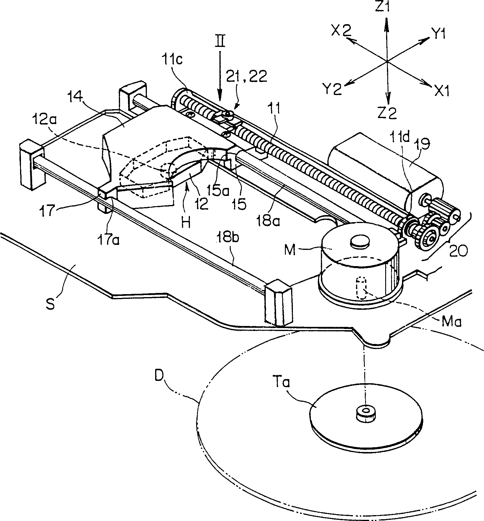
[0024] figure 1 It is a perspective view showing the whole of a disk drive unit for a digital video disk (DVD) with the optical head feeding device of the present invention mounted thereon facing upward. Such as figure 1 As shown, guide members (guide shafts) 18a, 18b are provided on the base plate S, and they are parallel to each other. The optical head unit H in which the optical head 12 is mounted is supported on the optical head base 14 between the guide members 18a, 18b. In the optical head 12, a light emitting element such as a semiconductor laser, an objective lens 12a, an element for receiving light, and other optical components are installed. The objective lens 12a collects the light emitted from the light-emitting element on the recording surface of the disc D, and the light-receiving element receives and detects the light reflected from the disc D.

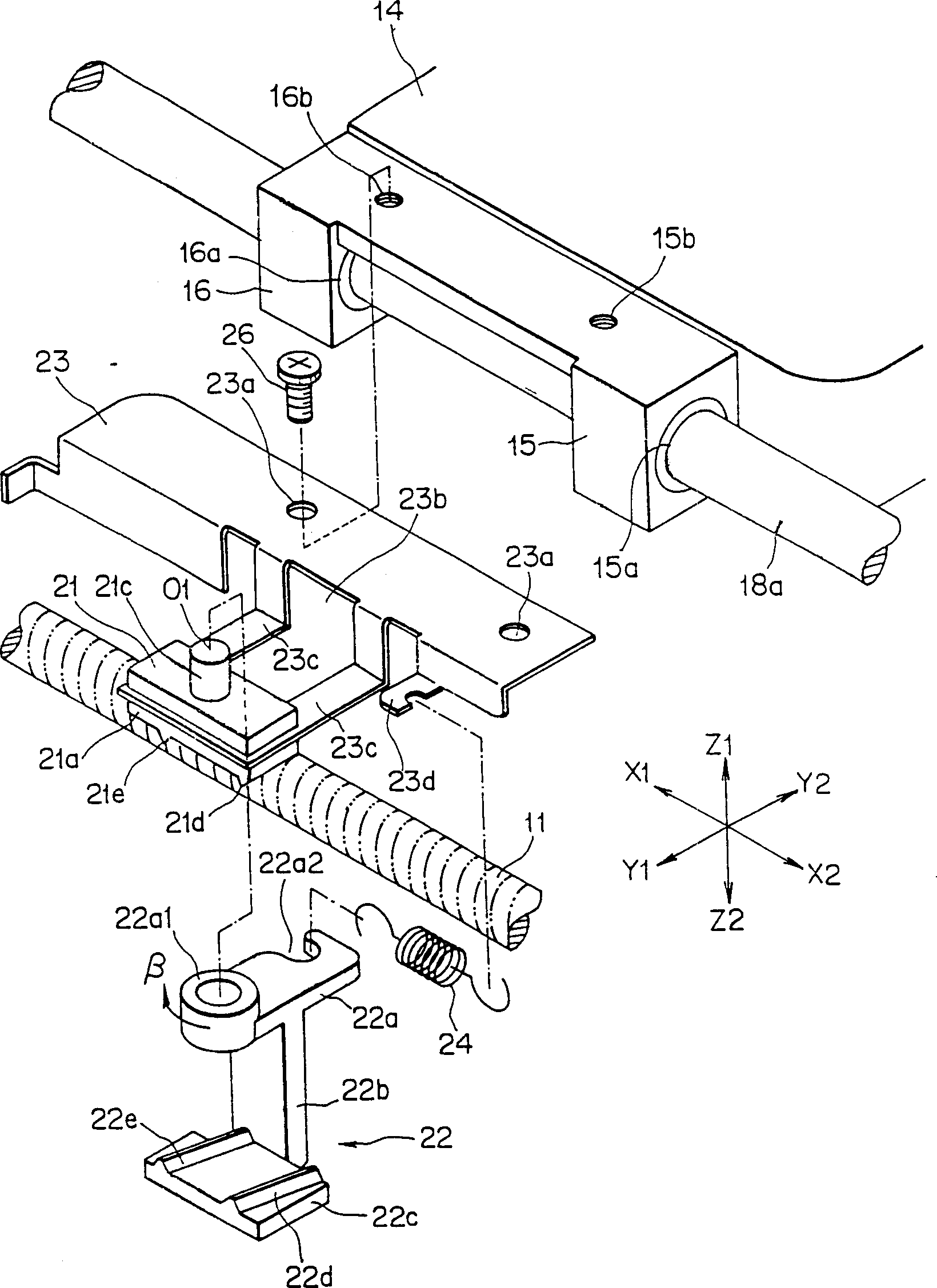
[0025] Bearing sleeves 15a, 16a are embedded in bearing portions 15, 16 integrally made on one side of the optic...


PUM


Abstract

The invention provides an optical head feeding device, which comprises an optical head part, a screw, a driving part and a thread engagement part. The thread engagement part consists of a first chimeric member and a second chimeric member. The first chimeric member is supported on the optical head, and is joggled with the screw. The second chimeric member is arranged at a position different from the position of the first chimeric member, and is joggled with the screw, and can move relative to the first chimeric member. In addition, the invention also comprises a force member which can apply an elastic compacting pressure on the two joggled members in two opposite directions towards the axial direction of the screw. Accordingly, the load of the screw is not increased, and the clearance between the two chimeric members and the screw can be absorbed.

Description

technical field [0001] The present invention relates to the feeding device of the optical head member of the reproducing head that is equipped with the information reproduction of recording media such as digital video disc (DVD) or laser disc (CD) and / or the recording head that information is recorded on the recording medium, In particular, it relates to an optical head feeder capable of reducing the gap between a screw and an optical head unit. Background technique [0002] Figure 6 It is a perspective view showing a feeding device of an optical head mounted on a playback unit for a conventional compact disk (CD). Figure 6 The optical head 2 of the shown optical head advancer with the objective lens 3 is guided by two guide shafts 8a, 8b. At one end of the optical head base 4 on which the optical head 2 is mounted, bearing holes 5a, 6a constituting guide references are formed, and a guide shaft 8a is inserted into and passes through the bearing holes 5a, 6a. In addition,...

Claims


Application Information

Patent Timeline
IPC IPC(8): G11B21/02G11B7/08
Inventor 加藤一成
Owner ALPINE ELECTRONICS INC
Features
  • Generate Ideas
  • Intellectual Property
  • Life Sciences
  • Materials
  • Tech Scout
  • Unparalleled Data Quality
  • Higher Quality Content
  • 60% Fewer Hallucinations
Learn More