Master selection method

A computing device and linear topology technology, applied in the computer field, can solve the problems of waste of power consumption, long distance of computing devices, large delay, etc., and achieve the effect of improving information interaction efficiency, wide utilization value, and minimum delay

Active Publication Date: 2022-07-01
沐曦科技北京有限公司
View PDF4 Cites 0 Cited by
  • Summary
  • Abstract
  • Description
  • Claims
  • Application Information

AI Technical Summary

Problems solved by technology

However, there are at least the following disadvantages in the existing technology: (1) The existing technology usually selects the master at random, which may cause some computing devices to be far away from the master, resulting in a large delay, which affects the efficiency of power allocation. Considering the delay of each computing device, however, since the number of computing devices may change, the original master can no longer guarantee a reasonable delay afte

Method used


Image

  • Master selection method
  • Master selection method
  • Master selection method

Examples


Example Embodiment

[0014] Embodiment 1.

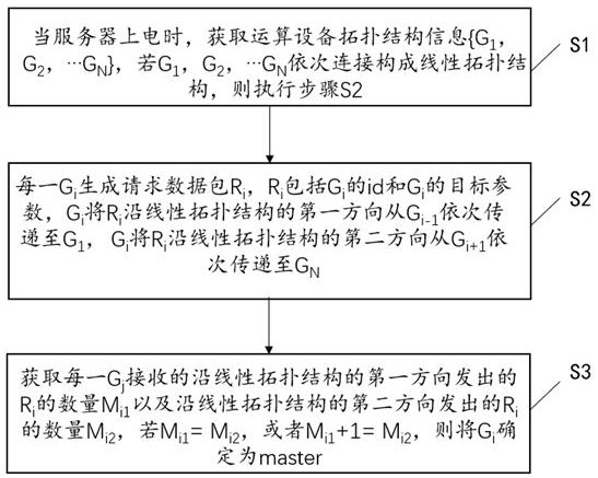
[0015] Embodiment 1 provides a method for selecting a master, which is applied to a scenario where multiple computing devices interact, such as figure 1 shown, including:

[0016] Step S1, when the server is powered on, obtain the computing device topology information {G 1 , G 2 ,…G N }, if G 1 , G 2 ,…G N Connect sequentially to form a linear topology structure, then execute step S2;

[0017] Among them, when the server is powered on, that is, when the server is started, when the computing devices inside the server need to increase, decrease or adjust the topology, the server needs to be shut down, and the number of computing devices needs to be adjusted and then powered on again. The method described in the embodiment can also adaptively determine the optimal master based on the current latest number of computing devices and the topology structure of computing devices. The server is specifically a single server or a cluster composed of multiple...

Example Embodiment

[0047] Embodiment two,

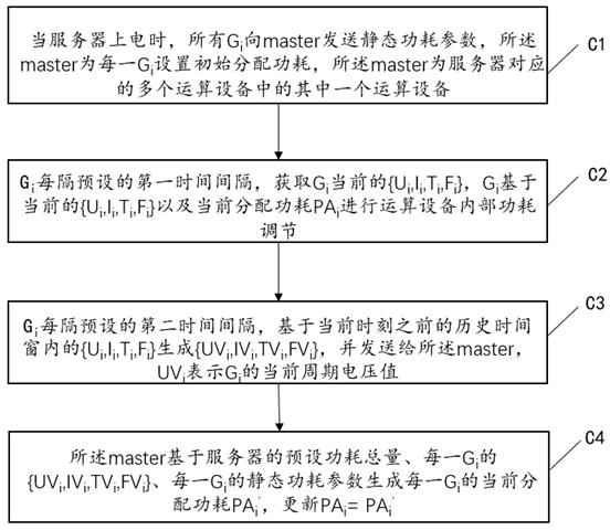
[0048] Embodiment 2 provides a method for allocating power consumption based on multiple computing devices, such as figure 2 shown, including:

[0049] Step C1. When the server is powered on, all G i Send static power consumption parameters to the master, the master is each G i Set the initial allocation power consumption, the master is one of the multiple computing devices corresponding to the server, G i is the i-th computing device in the server, the value of i ranges from 1 to N, and N is the total number of computing devices in the server;

[0050] where the initial allocated power can be based on G i The static power consumption parameters of the server and the total power consumption of the server can be directly allocated, or the default value can be set directly. Since the master can be quickly determined after power-on, the process of dynamically allocating power consumption will soon enter. Therefore, set a reasonable initial value. Al...


PUM


Abstract

The invention relates to a master selection method, which comprises the following steps: S1, when a server is powered on, acquiring topological structure information {G1, G2,... GN} of computing equipment, if G1, G2,... GN are sequentially connected to form a linear topological structure, executing the step S2, each Gi generates a request data packet Ri, the Ri comprises id of the Gi and target parameters of the Gi, the Gi sequentially transmits the Ri to G1 from Gi-1 along a first direction of the linear topological structure, and the Gi transmits the request data packet Ri to G1 from Gi-1 along a second direction of the linear topological structure; the Gi sequentially transmits the Ri to the GN from the Gi + 1 along the second direction of the linear topological structure; and S3, obtaining the number Mi1 of Ri emitted along the first direction of the linear topological structure and the number Mi2 of Ri emitted along the second direction of the linear topological structure received by each Gj, and if Mi1 is equal to Mi2 or Mi1 + 1 is equal to Mi2, determining Gi as master. According to the invention, the information interaction efficiency among a plurality of computing devices is improved.

Description

technical field [0001] The invention relates to the field of computer technology, and in particular to a master selection method. Background technique [0002] AI computing devices such as GPUs, FPGAs, DSPs, and AI accelerators in servers need to maintain power consumption near Thermal Design Power (TDP) during normal operation. Existing servers or server clusters usually include For multiple computing devices, how to reasonably allocate power consumption to the multiple computing devices is very important during the operation of the multiple computing devices. In the prior art, a master (main computing device) is usually selected among multiple computing devices, and power consumption is allocated to the multiple computing devices through the master. However, there are at least the following shortcomings in the prior art: (1) The prior art usually randomly selects the master, which may lead to a long distance between some computing devices and the master, resulting in a la...

Claims


Application Information

Patent Timeline
IPC IPC(8): H04L41/04G06F9/50
CPCH04L41/04G06F9/5027Y02D10/00
Inventor 不公告发明人
Owner 沐曦科技北京有限公司
Why Eureka
Try Eureka