Connecting device of audio equipment and audio equipment

A technology for audio equipment and connection devices, applied in the audio field, can solve problems such as high hardware docking costs and construction costs, affecting audio playback effects, and audio signal interference, so as to improve audio playback effects, improve audio signal quality, and reduce interference. Effect

Pending Publication Date: 2022-07-01
GUANGZHOU AIMYUNION NETWORK TECH
View PDF0 Cites 0 Cited by
  • Summary
  • Abstract
  • Description
  • Claims
  • Application Information

AI Technical Summary

Problems solved by technology

[0002] In traditional audio equipment usage scenarios, the combined use of various equipment is mostly scattered. For example, audio and video equipment arranged in KTV, restaurant private rooms and other commercial indoor scenes, including TVs, jukeboxes, effectors, wireless Microphone receivers, speakers, karaoke screens, microphones, etc., the distributed layout of various hardware requires on-site wiring, and the cost of hardware docking and construction is relatively high; and the use of multiple hardware products and multiple brands requires hard installation Electrical wiring, which brings a lot of inconvenient after-sales problems
[0003] At present, there are audio and video all-in-one devices on the market. Compared with traditional audio devices, these devices have improved in integration. However, these devices use different hardware and software and different wiring schemes in different scenarios, and still exist. The defect of complex wiring, in addition, these devices produced by different manufacturers are connected through different cables, and the ground ring effect will also be generated inside the cables, causing interference to the audio signal and seriously affecting the audio playback effect

Method used


Image

  • Connecting device of audio equipment and audio equipment
  • Connecting device of audio equipment and audio equipment
  • Connecting device of audio equipment and audio equipment

Examples


Embodiment Construction

[0028] The following describes in detail the embodiments of the present application, examples of which are illustrated in the accompanying drawings, wherein the same or similar reference numerals refer to the same or similar elements or elements having the same or similar functions throughout. The embodiments described below with reference to the accompanying drawings are exemplary and are only used to explain the present application, but not to be construed as a limitation on the present application.

[0029] It will be understood by those skilled in the art that the singular forms "a", "an", "the" and "the" as used herein can include the plural forms as well, unless expressly stated otherwise. It should be further understood that the word "comprising" as used in the specification of this application refers to the presence of the stated features, integers, steps, operations, but does not exclude the presence or addition of one or more other features, integers, steps, operation...


PUM


Abstract

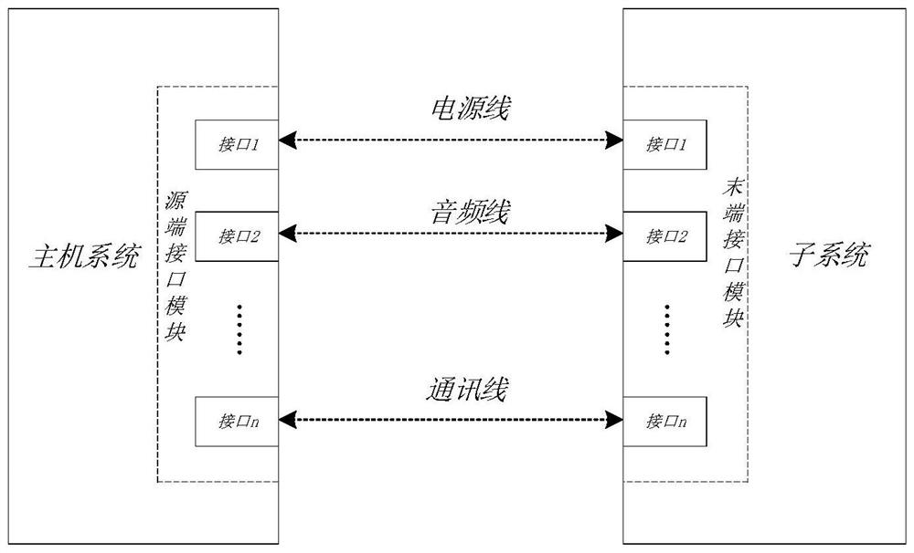
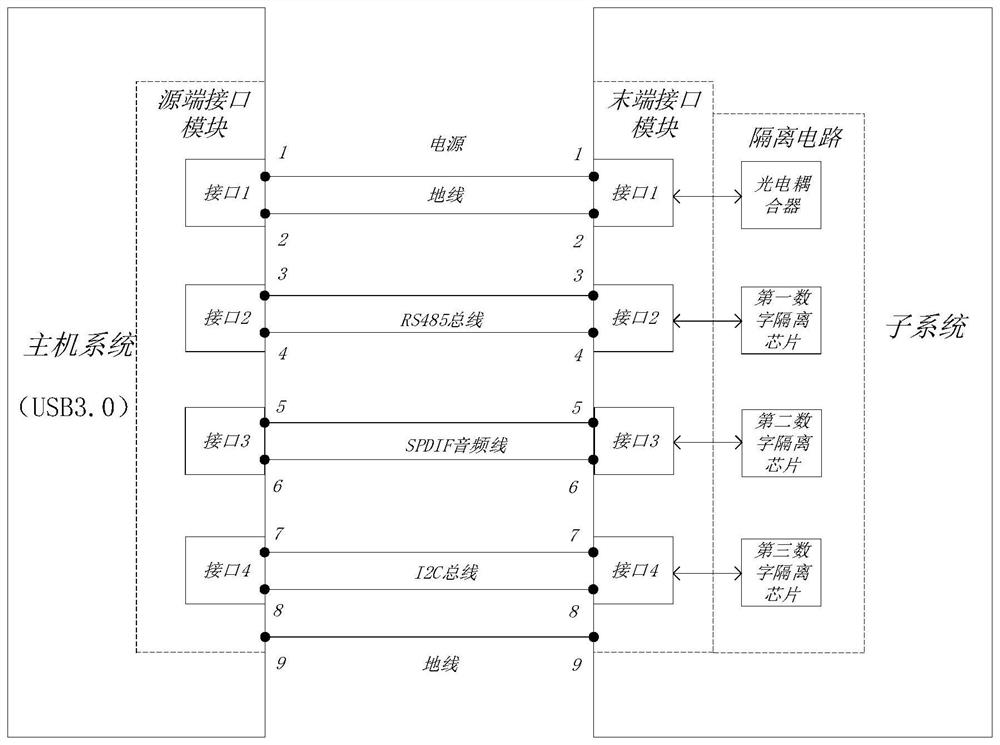
The invention relates to a connecting device of audio equipment and the audio equipment. The connecting device comprises a source end interface module arranged on a host system and a tail end interface module arranged on a subsystem, wherein the source end interface module comprises a first power interface, a first audio interface and a first communication interface; the tail end interface module comprises a second power interface, a second audio interface and a second communication interface; the source end interface module is connected with the tail end interface module through at least one multi-core cable, and any one multi-core cable is connected with at least two groups of the first power interface-second power interface, the first audio interface-second audio interface and the first communication interface-second communication interface. According to the technical scheme, the wiring complexity is reduced on the basis that the functions of power supply control, audio transmission and mutual communication of the host system and the subsystems are achieved, the ground ring effect in the cable is reduced through the multi-core cable, interference to audio signals is reduced, and the audio playing effect is improved.

Description

technical field [0001] The present application relates to the field of audio technology, in particular to a connecting device for audio equipment and audio equipment. Background technique [0002] In traditional audio equipment usage scenarios, the combined use of various equipment is mostly scattered. For example, audio and video equipment arranged in commercial indoor scenes such as KTV and restaurant private rooms, including TVs, jukeboxes, effects, wireless Microphone receivers, speakers, song-ordering screens, microphones, etc., the distributed arrangement of various hardware requires on-site wiring, and the cost of hardware connection and construction is relatively high; and the use of various hardware products and brands requires hard cloth Electrical wiring brings many inconvenient after-sales problems. [0003] At present, there are audio and video all-in-one devices on the market. Compared with traditional audio devices, these devices have improved integration. Ho...

Claims


Application Information

Patent Timeline
IPC IPC(8): H04R3/02
CPCH04R3/02
Inventor 周跃兵牟刚
Owner GUANGZHOU AIMYUNION NETWORK TECH
Why Eureka
Try Eureka