
Alternating current line fault determination method and system based on double-end transient quantity

A technology of AC line and determination method, which is applied in the direction of fault location, information technology support system, emergency protection circuit device, etc., can solve problems such as failure to detect faults, inability to fully meet the requirements of new power systems, and poor adaptability of traditional protection principles. Achieve the effect of high-speed and accurate fault identification

Pending Publication Date: 2022-07-05
NORTH CHINA ELECTRIC POWER UNIV (BAODING)
View PDF0 Cites 0 Cited by
  • Summary
  • Abstract
  • Description
  • Claims
  • Application Information

AI Technical Summary

Problems solved by technology

Because the new power system has a high proportion of new energy power sources and high proportion of power electronic equipment, the electrical characteristics of the system fault power frequency have also changed. At present, the power system still configures line protection schemes in a conventional way, and traditional protection principles begin to show poor adaptability. The problem
The traditional power frequency protection believes that the grid power supply voltage and short-circuit impedance remain constant at the moment of a fault, but the rapid adjustment of the control mode and topology of power electronic devices, the rapid change of the new energy power supply operation structure and control strategy, make the system power supply and short-circuit resistance after the fault occurs. The path changes instantaneously, resulting in the traditional protection based on power frequency electrical quantities. In this scenario, the fault cannot be detected, so it cannot fully meet the requirements of the new power system relay protection.

Method used


Image

  • Alternating current line fault determination method and system based on double-end transient quantity
  • Alternating current line fault determination method and system based on double-end transient quantity
  • Alternating current line fault determination method and system based on double-end transient quantity

Examples


Embodiment 1

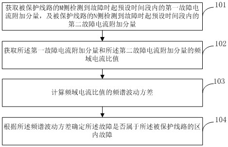
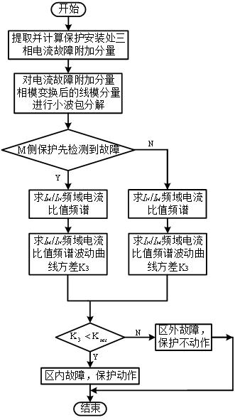
[0080] like figure 1 and 2 As shown, the embodiment of the present invention provides a method for determining AC line faults based on double-ended transients. The method of the present invention selects the variance of the frequency-domain current ratio spectrum fluctuation curve as the basis for fault identification inside and outside the area, and according to both sides When a fault is detected, a corresponding protection criterion element is selected, and the method includes the following steps:

[0081] Step 101: Obtain the first additional component of fault current within a preset time period from when the M side of the protected line detects a fault, and the second fault current within a preset time period from when the N side of the protected line detects a fault Additional component; wherein, the protected line is an AC line with protection devices installed at both ends (the two ends are M side and N side respectively), and the first additional component of fault ...

Embodiment 2

[0106] Embodiment 2 of the present invention provides a system for determining AC line faults based on double-ended transients, and the system includes:

[0107] The additional component acquisition module of fault current is used to obtain the first additional component of fault current within a preset time period from when a fault is detected on the M side of the protected line, and a preset time period from when a fault is detected on the N side of the protected line The second additional component of fault current in the circuit; wherein protection devices are installed on both the M side and the N side, and the first additional component of fault current is the actual current within a preset time period from when the M side of the protected line detects the fault The difference value from the current under no-fault condition within the preset time period, the additional component of the second fault current is the actual current within the preset time period from when the ...

Embodiment 3

[0122] The implementation principle of the method in Embodiment 1 of the present invention and the system in Embodiment 2 is:

[0123] 1. Analysis of fault transient current spectrum characteristics

[0124] (1) Analysis of fault characteristics in the area

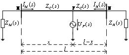
[0125] Fault additional networks in case of intra-area faults such as image 3 shown. in, U F ( s ) is the fault voltage source, I M ( s ), I N ( s ) are the measured values ​​of the protection currents on the M and N sides of the protected lines, respectively, Z M ( s ) is the equivalent impedance of the M-side system, Z N ( s ) is the equivalent impedance of the N-side system, Z C ( s ) is the wave impedance of the protected line, l For the full length of the protected line M-N, x is the distance between the fault point and the M side of the bus, l - x is the distance between the fault point and the N side of the bus.

[0126] From the analysis of the frequency component of the wave process of th...


PUM


Abstract

The invention relates to an alternating current line fault determination method and system based on a double-end transient state quantity, and belongs to power system line protection, and the method comprises the following steps: obtaining a first fault current additional component in a preset time period when a fault is detected at an M side of a protected line, and a second fault current additional component within a preset time period when the N side of the protected line detects a fault; acquiring a frequency domain current ratio of the first fault current additional component to the second fault current additional component; calculating the frequency spectrum fluctuation variance of the frequency domain current ratio; and determining whether the fault belongs to the internal fault of the protected line according to the frequency spectrum fluctuation variance. According to the method, fault identification based on instantaneous change of a system power supply and a short-circuit path after the fault occurs is realized, and the requirement of relay protection of a novel power system is met.

Description

technical field [0001] The invention relates to the technical field of power system line protection, in particular to a method and system for determining AC line faults based on double-terminal transients. Background technique [0002] The new power system is a power system with new energy as the main body. Since the new power system has a high proportion of new energy power sources and a high proportion of power electronic equipment, the electrical characteristics of the power frequency of the system have also changed. At present, the power system is still configured with line protection schemes in a conventional way, and the traditional protection principles have begun to show poor adaptability. The problem. The traditional power frequency protection considers that the grid power supply voltage and short-circuit impedance remain constant at the moment of the fault, while the rapid adjustment of the control mode and topology structure of power electronic devices, and the r...

Claims


Application Information

Patent Timeline
IPC IPC(8): G01R31/08H02H7/26
CPCG01R31/085G01R31/088H02H7/26Y04S10/52
Inventor 王增平褚璐胡加伟郑博文王彤徐潜
Owner NORTH CHINA ELECTRIC POWER UNIV (BAODING)
Learn More