Supercharge Your Innovation With Domain-Expert AI Agents!

Equipment state pushing method and system

A technology of equipment status and equipment, applied in the field of power grid system, can solve problems such as production scale adjustment, safe and reliable power supply, hidden dangers of economic and energy-saving operation, equipment failure, etc., and achieve the effect of economical and energy-saving operation guarantee

Pending Publication Date: 2022-07-05
LANGFANG POWER SUPPLY COMPANY STATE GRID JIBEI ELECTRIC POWER COMPANY +1
View PDF0 Cites 0 Cited by
  • Summary
  • Abstract
  • Description
  • Claims
  • Application Information

AI Technical Summary

Problems solved by technology

[0002] At present, the analysis of user-specific changes mainly relies on manual inspection of the operation and maintenance status, and problems cannot be found in time. The user-side special change equipment often has equipment operation problems caused by insufficient user operation and maintenance, production scale adjustment, or equipment failure. Safe and reliable power supply, economical and energy-saving operation bring hidden dangers, and even threaten the safe and stable operation of the main network

Method used


Image

  • Equipment state pushing method and system
  • Equipment state pushing method and system
  • Equipment state pushing method and system

Examples


Embodiment 1

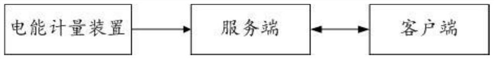
[0040] The present embodiment is a device state push method and system, wherein the device state push method is based on figure 1 As shown in the device state push system, the device state push system includes an electric energy metering device, a server and a client. The electric energy metering device is connected with the server, and the server is connected with the client.

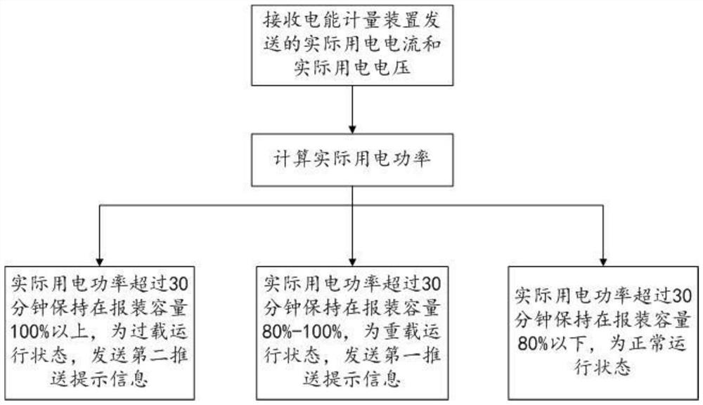
[0041] Wherein, the electric energy measuring device is an electric energy meter, which can collect voltage data and current data in real time, and send the real-time collected voltage data and current data to the server; it should be noted that the voltage and current data collected by the electric energy measuring device It is a 96-point collection method, and what it sends to the server is the total actual power consumption current and actual power consumption voltage of all devices of the user at the current moment; the so-called 96-point collection method refers to taking 96 points within 24 hours,...

Embodiment 2

[0065] On the basis of Embodiment 1, this embodiment further includes the following steps:

[0066] S6. When the time duration of the second timer reaches the second preset duration, send inquiry information to the client whether a regulation suggestion is required.

[0067] Specifically, when it is judged that it is in an overloaded operation state, when sending the second push prompt information, a query message of whether a regulation suggestion is required is sent to the client. At this time, the user can respond to the query information sent by the server through the client, that is, the user can choose to accept the regulation suggestion or not to accept the regulation suggestion.

[0068] S7. After receiving the control acceptance information sent by the user, the server obtains the device information sent by the client; generates a power consumption suggestion scheme according to the device information; and sends the power consumption suggestion scheme to the client te...


PUM


Abstract

The invention provides an equipment state pushing method and system. The method comprises the following steps: acquiring actual electricity utilization power; judging whether the actual electricity utilization power exceeds a first preset multiple of the installation capacity, and if yes, starting a first timer to start timing; judging whether the actual electricity utilization power exceeds a second preset multiple of the installation capacity, and if yes, starting a second timer to start timing; when the timing duration of the first timer reaches a first preset duration and the timing duration of the second timer does not reach a second preset duration, sending first push prompt information to the client; when the timing duration of the second timer reaches a second preset duration, sending second push prompt information to the client; the first preset multiple is smaller than the second preset multiple; the first preset duration is greater than or equal to the second preset duration; the power utilization health condition of the user can be monitored, the health problem of the power utilization equipment of the user can be found in time, the monitoring result is visually and actively pushed to the user as data, and safe and stable operation of a main network is facilitated.

Description

technical field [0001] The present application relates to the technical field of power grid systems, and in particular, to a device status push method and system. Background technique [0002] At present, the analysis of user-specific changes mainly relies on manual inspection of the operation and maintenance status, and problems cannot be found in time. User-side special-purpose equipment often has equipment operation problems caused by insufficient user operation and maintenance, production scale adjustment or equipment failure. Safe and reliable power supply, economical and energy-saving operation bring hidden dangers, and even threaten the safe and stable operation of the main network. Therefore, there is an urgent need to provide a device state push method and system. SUMMARY OF THE INVENTION [0003] The purpose of the present application is to provide a device status push method and system for the above problems. [0004] In a first aspect, the present application...

Claims


Application Information

Patent Timeline
Patent Type & Authority Applications(China)
IPC IPC(8): G06Q10/00G06Q50/06
CPCG06Q10/20G06Q50/06
Inventor 陈鹏宇陈硕张宝成宋良池周旭张影芳马力王玮韩雪辉
Owner LANGFANG POWER SUPPLY COMPANY STATE GRID JIBEI ELECTRIC POWER COMPANY
Features
  • R&D
  • Intellectual Property
  • Life Sciences
  • Materials
  • Tech Scout
  • Unparalleled Data Quality
  • Higher Quality Content
  • 60% Fewer Hallucinations
Learn More