
Patsnap Eureka
For R&D, Patsnap Eureka makes reading and utilizing patents & technical documents easy.
Patsnap Eureka AIR
Designed for self-driven R&D workflows. Generate viable solutions, solve complex R&D challenges, empower your innovation with AI.

Patsnap Eureka Materials
Designed for material experts only. Revolutionize your material R&D, from search, analyze, to developing new materials.

TechResearch
Generate reliable direction feasibility study reports for your R&D in just a few steps.

TechSeek
Discover and master advanced knowledge NOW. Basics, ideas, possibilities, all at once.

TechMind
As an expert in R&D Theories, TechMind can generates customized viable solutions instantly.

TechRisk
Analyze your overall solution with one click, know your potential R&D risks in advance.

TechMonitor
Get weekly tech updates, stay abreast of the latest tech innovations and key insights.
Mesh belt type screen exchanger
A technology of screen changer and mesh belt, applied in the field of screen changer, can solve the problems of filter screen pressure increase, filter screen belt pulling, filter screen deformation, etc., to prevent deformation, protect the rotating rod, and prevent impact deformation Effect
- Summary
- Abstract
- Description
- Claims
- Application Information
AI Technical Summary
Problems solved by technology
Method used
Image

Examples
Embodiment 1
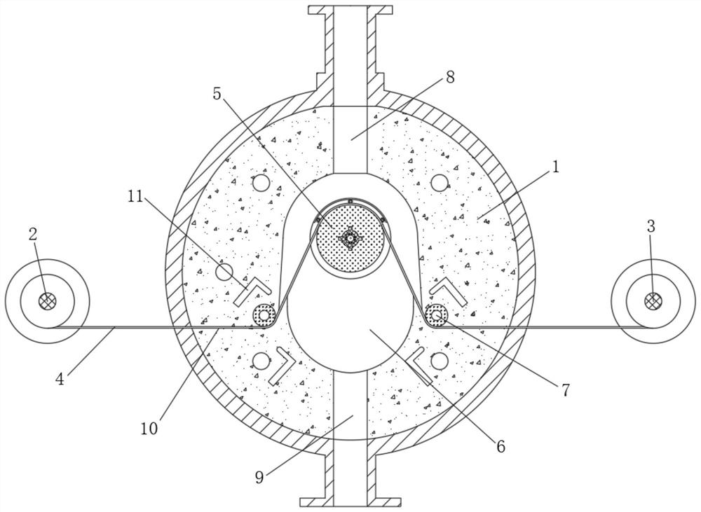
[0031] A mesh belt type screen changer, the screen changer includes an inner layer 1, a mesh belt 4, a column 5 and an upper cover 12
[0032] The two sides of the inner layer 1 are provided with a net trough 10, the outer side of the inner layer 1 is symmetrically provided with a pair of rotating winding rollers 2 and unwinding rollers 3, the middle of the inner layer 1 is vertically rotated and installed with a column 5, and the net trough 10 A pair of rotatably installed guide rollers 7 are arranged on both sides of the upright column 5, and a filter inner cavity 6 is arranged in the middle of the inner layer 1. The two sides of the filter inner cavity 6 are connected to the mesh slot 10, and the upright column 5 is installed in the filter inner cavity 6. In the middle, the inner layer 1 is provided with temperature control grooves 11 located on both sides of the mesh groove 10 .
[0033] A column 5 and a guide roller 7 are arranged in the middle of the mesh belt 4 to form ...
Embodiment 2
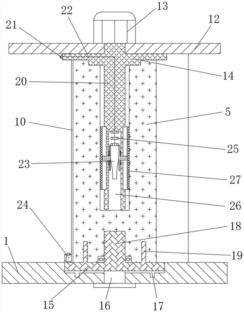
[0039] On the basis of Example 1, in order to improve the tightness of the lower end of the upright column 5 and prevent leakage of raw materials from unfiltered, affecting the quality of filtration, the present application also has a discharge port 9 and a feeding port on the front and rear sides of the filter cavity 6. Port 8, the lower end of the filter cavity 6 is provided with a base 15, the base 15 is sealed and installed on the inner wall of the lower end of the inner layer 1 through a fixed column 16, the lower end of the column 5 is rotated and installed on the base 15, and the column 5 is located close to the feed port 8 The upper end of the base 15 is vertically provided with a lower pin 18, a circular sealing ring 17 is pressed between the lower end of the base 15 and the inner wall of the lower end of the filter cavity 6, and the upper end surface of the base 15 is provided with The annular sealing drum 19 located on the outside of the lower pin 18, the lower end o...
Embodiment 3
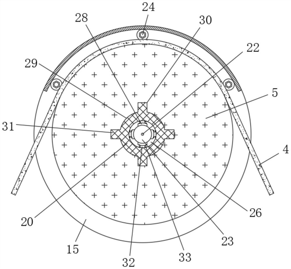
[0042] On the basis of Example 2, in order to prevent the raw material from falling and cooling and causing bonding with the lower end of the mesh belt 4, making it difficult for the mesh belt 4 to drive laterally, the present application also has a setting on the side of the upper end of the base 15 close to the feed port 8 There are three groups of heated bottom rollers 24, the heated bottom rollers 24 are located on the outside of the column 5, and there is a gap between the heated bottom roller 24 and the arc outer wall of the column 5, the mesh belt 4 slides through the gap, and the upper end of the driving rod 20 is set There is a baffle 14 , the outer diameter of the baffle 14 is larger than the outer diameter of the column 5 , and the baffle 14 is pressed against the upper end surface of the column 5 .
[0043] The position of the mesh belt 4 is limited by setting the baffle 14 and the heated bottom roller 24 , and the heated bottom roller 24 is used to heat the raw mat...
PUM
 Abstract
Description
Claims
Application Information
 - R&D Engineer
- R&D Manager
- IP Professional
- Industry Leading Data Capabilities
- Powerful AI technology
- Patent DNA Extraction
Browse by: Latest US Patents, China's latest patents, Technical Efficacy Thesaurus, Application Domain, Technology Topic, Popular Technical Reports.
© 2024 PatSnap. All rights reserved.Legal|Privacy policy|Modern Slavery Act Transparency Statement|Sitemap|About US| Contact US: help@patsnap.com