
Motor cleaning device

A technology for cleaning equipment and motors, applied in cleaning methods and utensils, cleaning methods using gas flow, chemical instruments and methods, etc., can solve problems such as poor cleaning effect

Active Publication Date: 2022-07-08
长沙振安机电设备有限公司
View PDF20 Cites 0 Cited by
  • Summary
  • Abstract
  • Description
  • Claims
  • Application Information

AI Technical Summary

Problems solved by technology

For this reason, the present invention proposes a motor cleaning device to solve the problem of poor cleaning effect of traditional motor cleaning devices

Method used


Image

  • Motor cleaning device
  • Motor cleaning device
  • Motor cleaning device

Examples


Embodiment Construction

[0039] The following describes in detail the embodiments of the present invention, examples of which are illustrated in the accompanying drawings, wherein the same or similar reference numerals refer to the same or similar elements or elements having the same or similar functions throughout. The embodiments described below with reference to the accompanying drawings are exemplary, only used to explain the present invention, and should not be construed as a limitation of the present invention.

[0040] In the description of the present invention, it should be understood that the terms "center", "longitudinal", "lateral", "length", "width", "thickness", "upper", "lower", "front", " Rear, Left, Right, Vertical, Horizontal, Top, Bottom, Inner, Outer, Axial, Radial, Circumferential The orientation or positional relationship indicated by etc. is based on the orientation or positional relationship shown in the accompanying drawings, which is only for the convenience of describing the...


PUM


Abstract

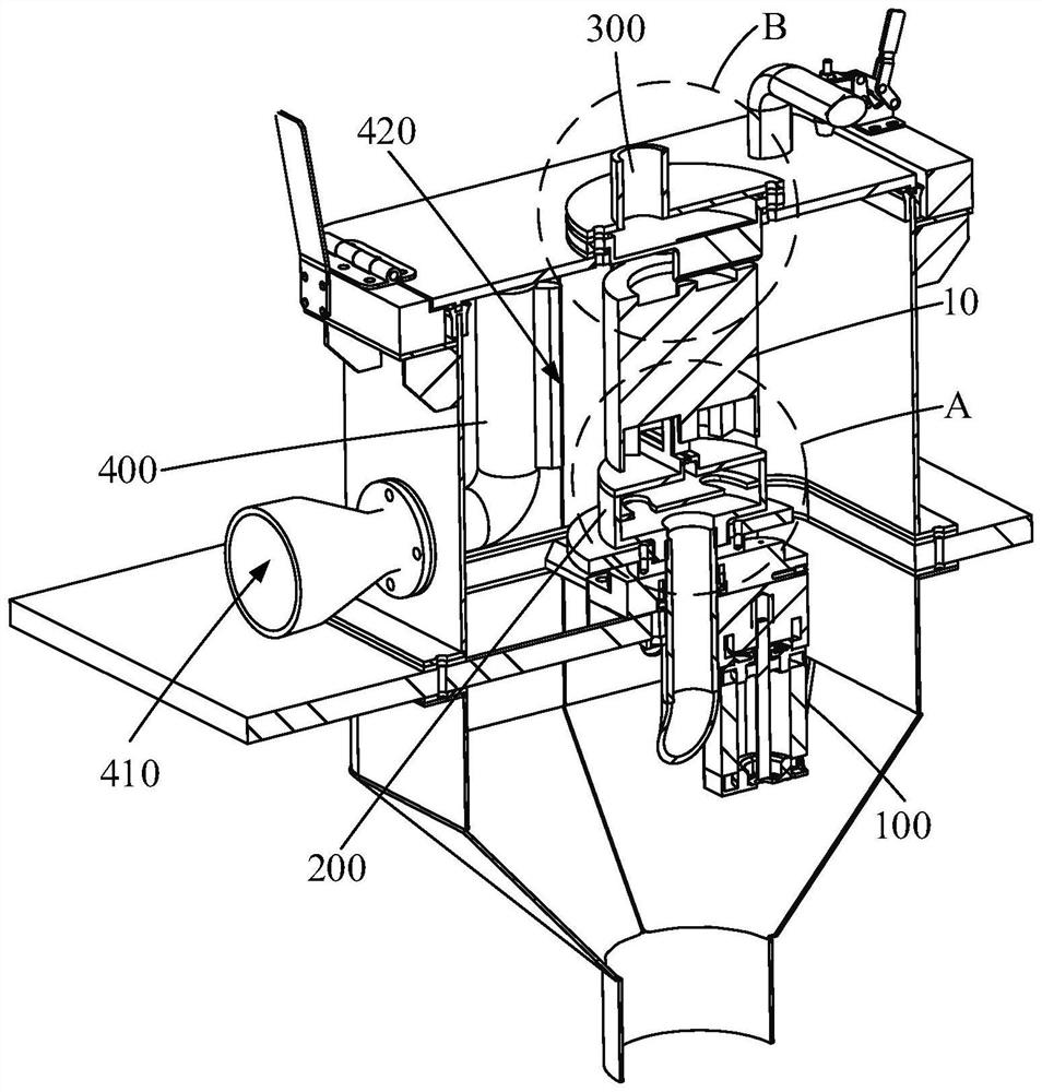
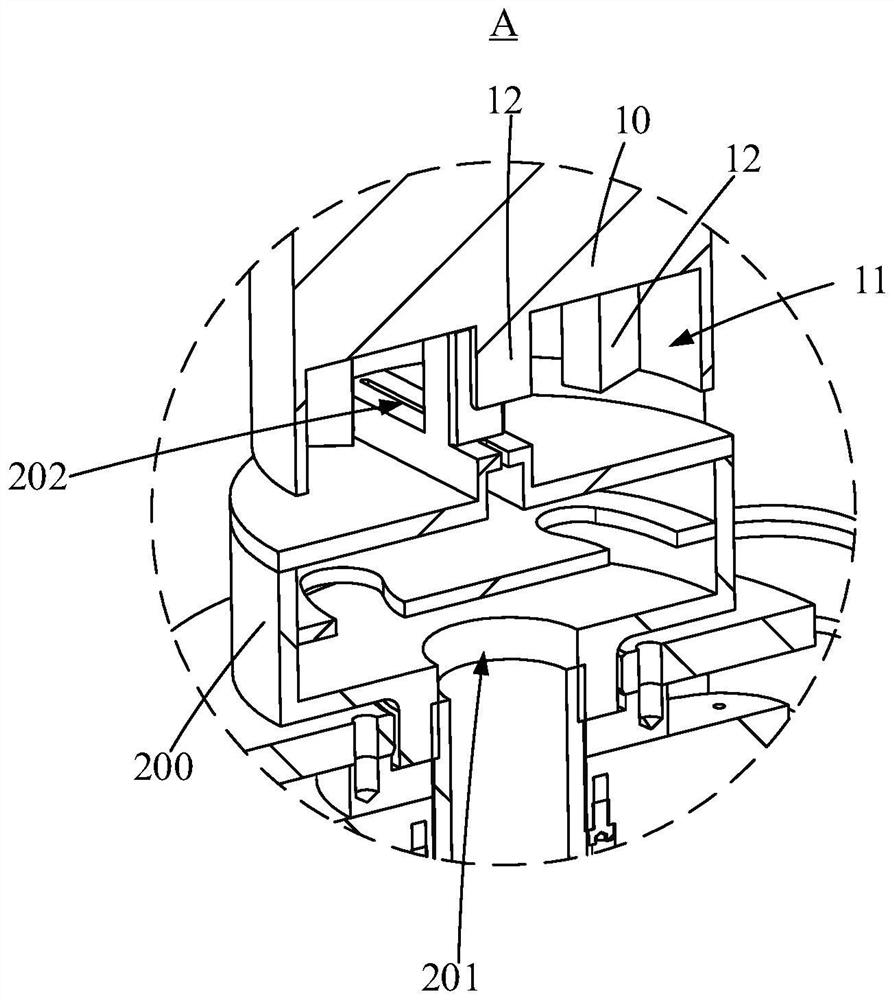
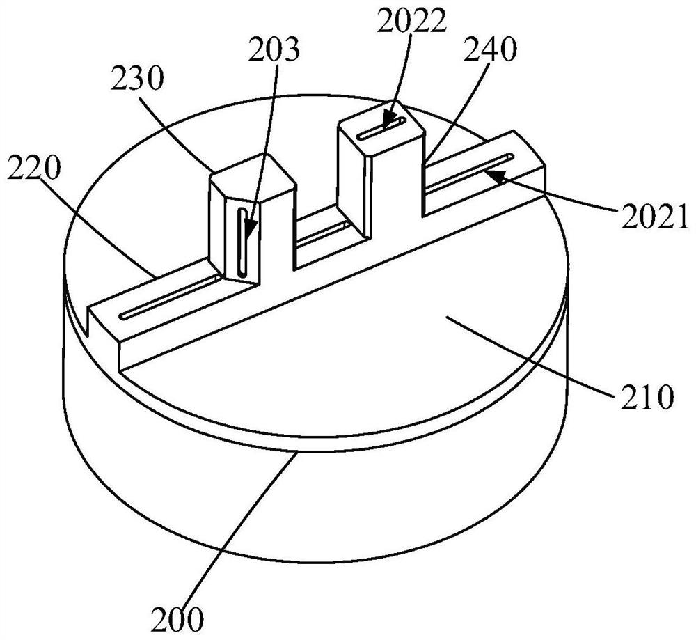
The invention discloses a motor cleaning device which comprises a rotary driving part used for being in driving connection with a motor, and the rotary driving part can drive the motor to rotate around the axis of the motor; the first air knife is provided with a first air inlet channel, a first air knife edge communicated with the first air inlet channel and a second air knife edge communicated with the first air inlet channel, the first air knife edge is used for being arranged towards the bottom wall of the groove in the first end of the motor, and the second air knife edge is used for being arranged towards the side wall of the groove; the second air knife is provided with a second air inlet channel and a third air knife edge communicated with the second air inlet channel, and the third air knife edge is used for being arranged towards the second end of the motor; the third air knife is provided with a third air inlet channel and a fourth air knife edge communicated with the third air inlet channel, and the fourth air knife edge is used for being arranged towards the side wall of the motor; and the fan is used for supplying air to the first air inlet channel, the second air inlet channel and the third air inlet channel.

Description

technical field [0001] The present invention relates to the technical field of motor cleaning, in particular to a motor cleaning device. Background technique [0002] The motor is a common power device. During the manufacturing process, some contaminants such as cuttings and dust particles will adhere to the motor. Therefore, it is necessary to clean the motor. [0003] Most of the traditional methods of cleaning the motor are to directly use a rag to clean the surface of the motor, which is troublesome to operate and has poor cleaning effect. [0004] At present, there is also a special equipment for cleaning the motor on the market. It uses a blower to form a cyclone around the motor to clean the side wall of the motor. The cleaning effect on the side wall of the motor is not good, and the The end is cleaned, and the cleaning effect is not ideal. SUMMARY OF THE INVENTION [0005] The present invention aims to solve at least one of the technical problems existing in the...

Claims


Application Information

Patent Timeline
IPC IPC(8): B08B5/02B08B13/00
CPCB08B5/023B08B13/00
Inventor 谌剑宋杰
Owner 长沙振安机电设备有限公司
Learn More