Machine for conveying multiple U-shaped steel bars

A steel bar, U-shaped technology, used in metal processing machinery parts, metal processing, measuring/indicating equipment, etc., can solve problems such as reduced work efficiency, shaking at both ends of the steel bar, inability to accurately convey the length, etc., to improve work efficiency, reduce The effect of labor costs

Pending Publication Date: 2022-07-08
RBS PARTNERS S&T CO LTD
View PDF0 Cites 0 Cited by
  • Summary
  • Abstract
  • Description
  • Claims
  • Application Information

AI Technical Summary

Problems solved by technology

[0002] In the process of building construction, steel bars need to be used, and the steel bars need to be transported and loaded in the processing process of different procedures. During the process of transport, the length of the transport cannot be accurately conveyed, and manual continuous handling and adjustment are required. Secondly, in the When the steel bars are placed, due to the action of gravity, the steel bars will be tilted, resulting in the failure of transmission. At the same time, when the steel bars are too long, it is easy to have the problem of shaking at both ends. At present, the steel bars on the market are mainly transported by a single piece. For the existing U-shaped steel bars cannot satisfy multiple feeding at one time, which reduces work efficiency

Method used


Image

  • Machine for conveying multiple U-shaped steel bars
  • Machine for conveying multiple U-shaped steel bars
  • Machine for conveying multiple U-shaped steel bars

Examples


Embodiment Construction

[0032] The following will combine Figure 1-13 The present invention is described in detail, and the exemplary embodiments and descriptions of the present invention are used to explain the present invention, but not to limit the present invention.

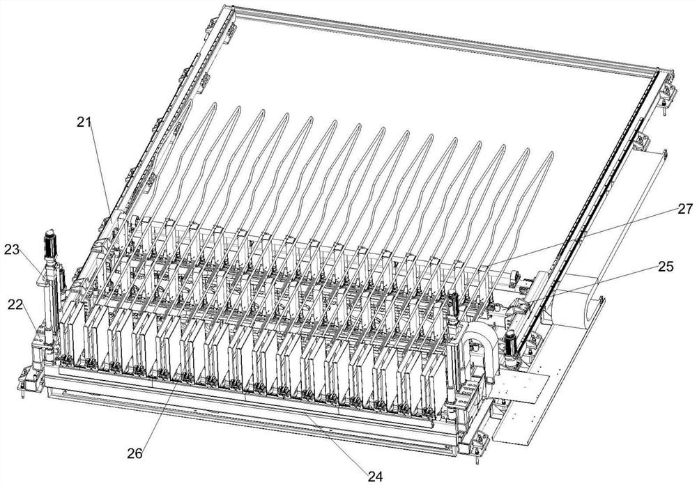
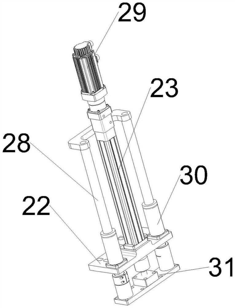
[0033]A multiple conveying machine for U-shaped steel bars, which includes a frame 21, a base plate 22 is fixed on the tops of both sides of the frame, a linear bearing 30 and an electric cylinder 23 are arranged on the base plate, and the linear bearing is internally sleeved. The guide rod shaft 28 is connected, and the top of the electric cylinder is provided with a first servo motor. On the bracket 24, several sliding feeding mechanisms 26 are arranged on the first bracket, and at least one second bracket 25 parallel to the first bracket is also arranged between the racks, and several second brackets are arranged on the second bracket. A material holding mechanism 27, one end of each described feeding mechanism is slidably inst...


PUM


Abstract

The machine comprises a rack, base plates are fixedly arranged at the tops of the two sides of the rack, linear bearings and electric cylinders are arranged on the base plates, guide rod shafts are connected into the linear bearings in a sleeved mode, first servo motors are arranged at the tops of the electric cylinders, and the guide rod shafts and output shafts of the electric cylinders penetrate through the base plates to be connected with load mounting plates. The load mounting plate is arranged on a first support, a plurality of sliding feeding mechanisms are arranged on the first support, at least one second support parallel to the first support is further arranged between the racks, and a plurality of material supporting mechanisms are arranged on the second support. The feeding mechanisms drive the first enclasping devices to move through the first dial-up assemblies to achieve interval adjustment on the first support, and the supporting mechanisms drive the second enclasping devices to move through the second dial-up assemblies to achieve interval adjustment on the second support. Fixed-length conveying of a plurality of U-shaped steel bars is achieved, the U-shaped steel bars with openings of different widths are compatible, and flexible torque changing between the U-shaped steel bars can be achieved.

Description

technical field [0001] The invention relates to the field of steel bar conveying equipment, in particular to a U-shaped steel bar multiple conveying machine. Background technique [0002] In the process of building construction, steel bars need to be used, and steel bars need to be conveyed and loaded during the processing of different procedures. During the conveying process, the length cannot be conveyed accurately, and manual handling and adjustment are required. When the steel bars are placed, due to the effect of gravity, the steel bars are inclined, which makes it impossible to transmit. At the same time, when the steel bars are too long, the problem of shaking at both ends is prone to occur. At present, the steel bars on the market are mainly conveyed by a single piece. U-shaped steel bars cannot meet the requirements of multiple feedings at one time, which reduces work efficiency. SUMMARY OF THE INVENTION [0003] In view of the above problems, the present inventi...

Claims


Application Information

Patent Timeline
Patent Type & Authority Applications(China)
IPC IPC(8): B23Q7/14B23Q17/20
CPCB23Q7/1478B23Q17/20
Inventor 刘付钧刘紫敬李祖保赵中文罗聿侃戴昆
Owner RBS PARTNERS S&T CO LTD
Why Eureka
Try Eureka