Combustor thermocouple convenient to clean
A thermocouple and burner technology, applied in the direction of using electric devices, using electromagnetic means, cleaning methods and appliances, etc., can solve the problems that the outer wall of the protection tube is easy to absorb impurities and inconvenient to clean, and achieve good fixing effect, stable movement, and prevent shaking effect
- Summary
- Abstract
- Description
- Claims
- Application Information
AI Technical Summary
Problems solved by technology
Method used
Image

Examples
Embodiment 1
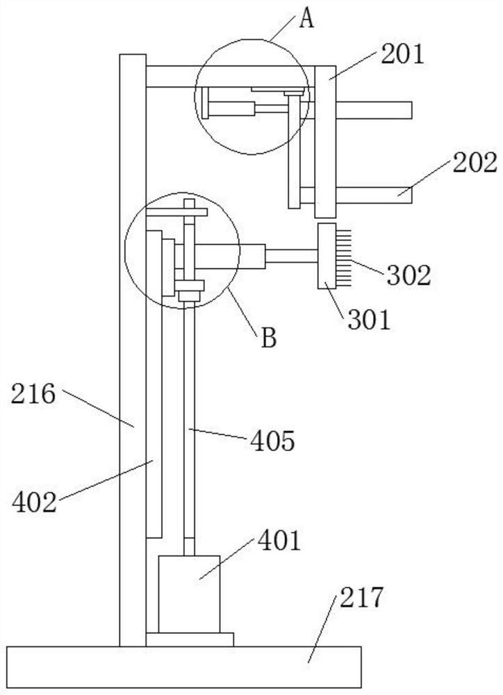
[0036] like Figure 1-6 As shown, a thermocouple for a burner that is easy to clean includes a thermocouple main body 1; a fixing mechanism 2 for fixing the thermocouple main body 1; Cleaning; the driving mechanism 4 is used to drive the cleaning mechanism 3 ; the thermocouple main body 1 includes a junction box 5 and a protection tube 6 .
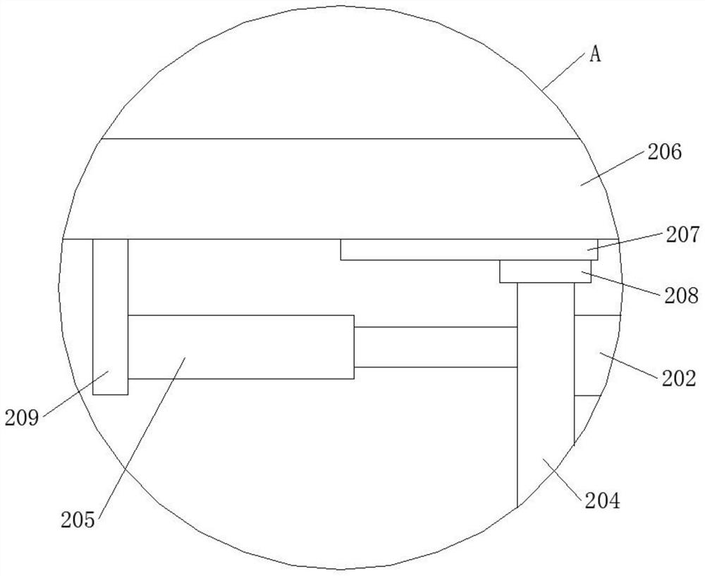
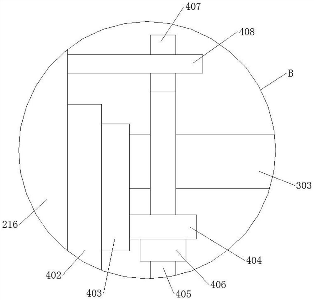
[0037] The fixing mechanism 2 includes a support plate 201 and two U-shaped fixing rods 202. The side wall of the support plate 201 is matched with a through hole 203 of the U-shaped fixing rod 202. The U-shaped fixing rod 202 passes through the through hole 203, and the two U-shaped fixing rods One end of the rod 202 is provided with the same first connecting plate 204 , and the side wall of the first connecting plate 204 is provided with a first electric push rod 205 . The top of the side wall of the support plate 201 is provided with a second connecting plate 206, the bottom of the second connecting plate 206 is provided with a second ...
Embodiment 2
[0042] like Figure 6-9 As shown, a thermocouple for a burner that is easy to clean includes a thermocouple main body 1; a fixing mechanism 2 for fixing the thermocouple main body 1; Cleaning; the driving mechanism 4 is used to drive the cleaning mechanism 3 ; the thermocouple main body 1 includes a junction box 5 and a protection tube 6 .
[0043] The fixing mechanism 2 includes a first fixing plate 210 and a second fixing plate 211. The top of the first fixing plate 210 is provided with a third connecting plate 212, and the bottom of the third connecting plate 212 is provided with a third electric push rod 213. The third electric push rod 213 is connected to the second fixing plate 211 . The top of the third connecting plate 212 is provided with a second rotating shaft 214 , one end of the second rotating shaft 214 is provided with a fourth connecting plate 215 , a top plate 218 is disposed between the third connecting plate 212 and the fourth connecting plate 215 , and a c...
PUM
 Abstract
Description
Claims
Application Information
 - R&D Engineer
- R&D Manager
- IP Professional
- Industry Leading Data Capabilities
- Powerful AI technology
- Patent DNA Extraction
Browse by: Latest US Patents, China's latest patents, Technical Efficacy Thesaurus, Application Domain, Technology Topic.
© 2024 PatSnap. All rights reserved.Legal|Privacy policy|Modern Slavery Act Transparency Statement|Sitemap