Capless multiaxial screw and spinal fixation assembly and method

a multi-axial screw and screw technology, applied in the field of spinal fixation assembly and method, can solve the problems of spinal rod threading, spinal rod threading, number of parts and components, etc., and achieve the effect of improving spinal fixation

Active Publication Date: 2007-02-22
X SPINE SYST
View PDF99 Cites 207 Cited by
  • Summary
  • Abstract
  • Description
  • Claims
  • Application Information

AI Technical Summary

Benefits of technology

[0013] The present invention improves the spinal fixation...

Problems solved by technology

However, in many cases, in particular cases involving fusion across the lumbosacral articulation and where there are many levels involved, pseudorarthrosis is a problem.
One detriment of the systems in the two Harms et al. patents is that the spinal rod must be threaded in order to accept the compression nuts.
One of the problems with the prior art devices is the number of parts and components, especially those ...

Method used


Image

  • Capless multiaxial screw and spinal fixation assembly and method
  • Capless multiaxial screw and spinal fixation assembly and method
  • Capless multiaxial screw and spinal fixation assembly and method

Examples


Embodiment Construction

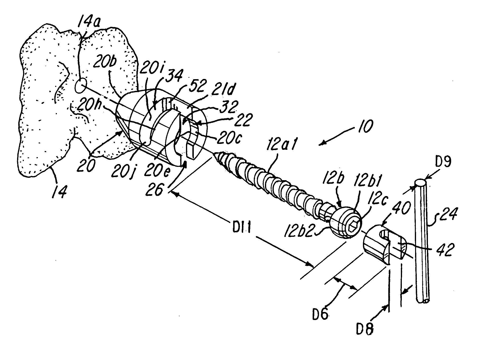
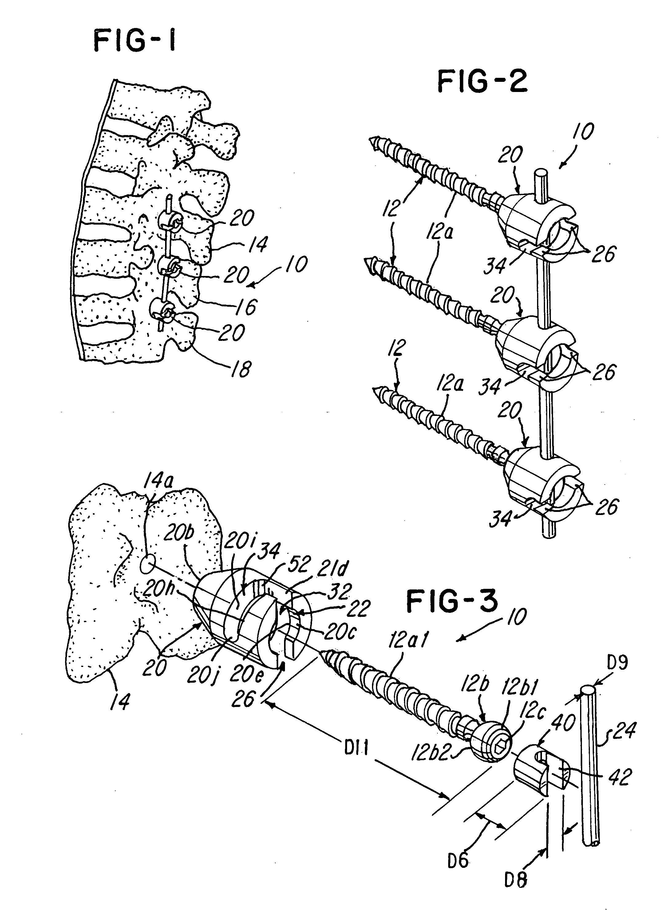
[0049] Referring now to FIGS. 1-3, a capless multi-axial screw and spinal fixation assembly 10 and method are shown. The assembly 10 comprises a screw 12 having a threaded portion 12a and a head 12b that in the embodiment being described, has a rounded profile or curvature, as best illustrated in FIGS. 3 and 10-13. The screw head 12b comprises a hex female opening 12c for receiving a tool (not shown) for screwing the screw 12 into an aperture 14a of a spinal bone 14, such as a vertebra of a spine.

[0050] As illustrated in FIGS. 1 and 2, one feature of the invention is that it enables a user to fix a relative position of a plurality of vertebrae, such as vertebrae 14, 16 and 18 in FIG. 1, in a fixed and stabilized position.

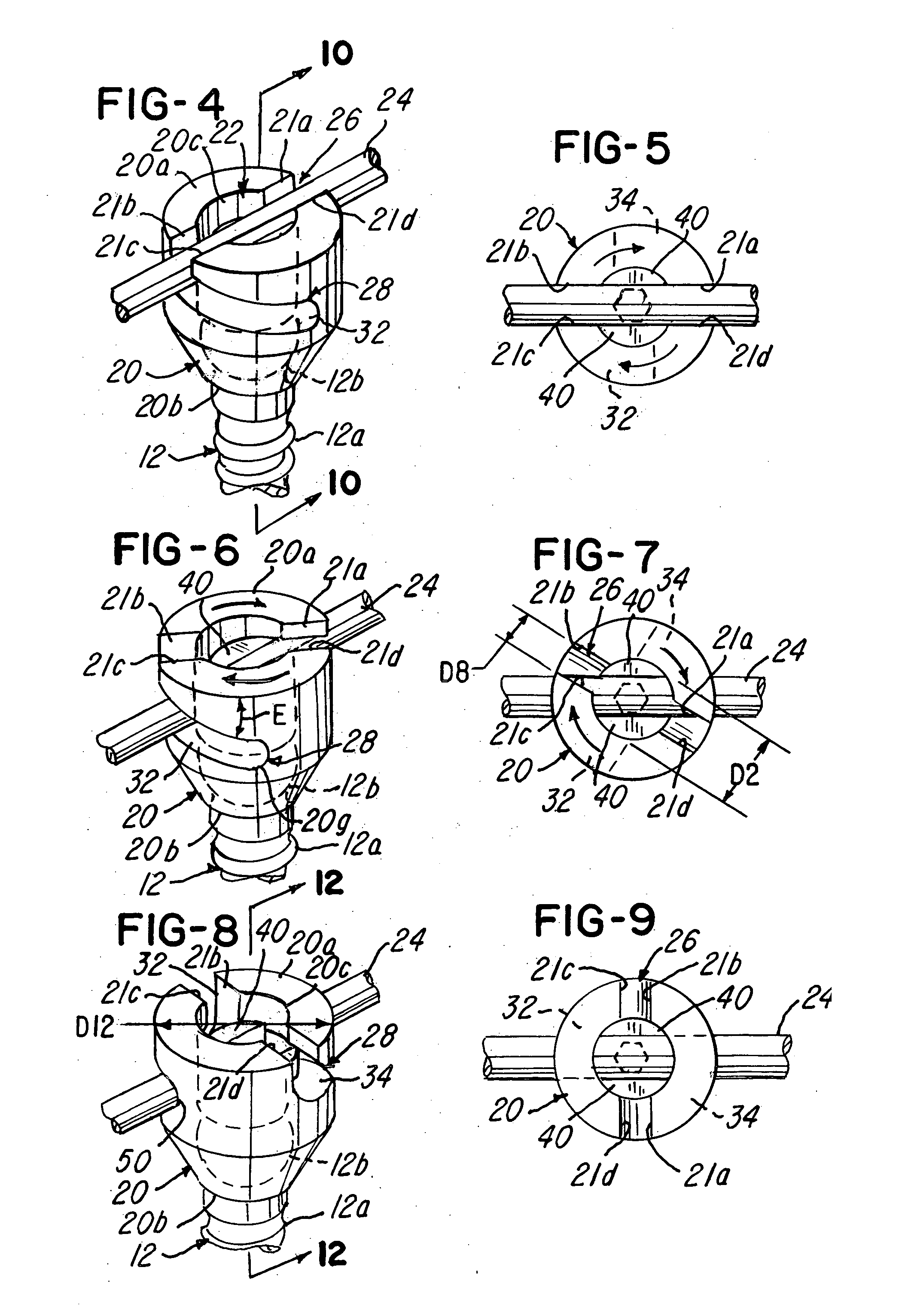
[0051] The system 10 comprises a retainer or receiver 20 having a generally cylindrical receiver wall 20c (FIG. 4) that defines an aperture or bore 22 that traverses or extends along a receiver axis A (FIG. 11) the entire length of the receiver 20, as best illustr...


PUM


Abstract

A spinal fixation assembly and capless multi-axial screw system and method are shown. The assembly comprises a receiver having a rotary lock which in one embodiment includes a plurality of channels which urge and lock the elongated member to the screw using a bayonet type connection.

Description

BACKGROUND OF THE INVENTION [0001] This invention relates to a capless multiaxial screw and spinal fixation assembly and method, particularly useful for fixing and / or aligning vertebrae of the spine. The invention permits multiple angular orientations of an elongated member or rod with respect to a screw that is screwed into a vertebra. [0002] Various methods of spinal immobilization have been known and used in the past. The preferred treatment for spinal stabilization is immobilization of the joint by surgical fusion or anthrodesis. This method has been known since development in 1911 by Hibbs and Albe. However, in many cases, in particular cases involving fusion across the lumbosacral articulation and where there are many levels involved, pseudorarthrosis is a problem. It was discovered that immediate immobilization was necessary in order to allow a bony union to form. Post operative external immobilization, such as the use of splints and casts, was a favored method of treatment, ...

Claims


Application Information

Patent Timeline
IPC IPC(8): A61F2/30
CPCA61B17/7032A61B17/7037A61B17/7002
Inventor KIRSCHMAN, DAVID LOUIS
Owner X SPINE SYST
Why Eureka
Try Eureka