Valve for fluid pressure equipment

A technology for fluid pressure equipment and valves, which is applied in the direction of fluid pressure actuation devices, mechanical equipment, multi-way valves, etc., and can solve the problem of unintentionally maintaining manual shafts, etc.

Pending Publication Date: 2022-07-15
CKD
View PDF2 Cites 0 Cited by
  • Summary
  • Abstract
  • Description
  • Claims
  • Application Information

AI Technical Summary

Problems solved by technology

However, if the valve for fluid pressure equipment is a lock specification that can hold the position of the manual shaft after the manual shaft is moved relative to the housing to the position where the first valve body and the second valve body are in the valve-open state respectively, even There is also concern about the problem of unintentionally maintaining the position of the manual axis in cases where it is not necessary to maintain the position of the manual axis

Method used


Image

  • Valve for fluid pressure equipment
  • Valve for fluid pressure equipment
  • Valve for fluid pressure equipment

Examples


Embodiment Construction

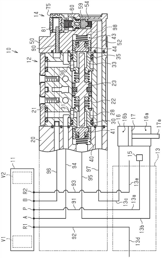
[0030] Below, according to Figure 1 to Figure 11(b) An embodiment of the valve for fluid pressure equipment will be described. The valve for fluid pressure equipment of the present embodiment is mounted on a solenoid valve manifold. Solenoid valve manifolds are used to supply or exhaust fluid to fluid pressure equipment.

[0031] like figure 1 As shown, the solenoid valve manifold 10 includes a solenoid valve 11 , a pilot-operated check valve 12 , a manifold base 13 , and a valve 14 for fluid pressure equipment. The solenoid valve 11 has a supply port P, a first output port A, a second output port B, a first discharge port R1, and a second discharge port R2. Therefore, the solenoid valve 11 of the present embodiment is a five-way solenoid valve.

[0032] The solenoid valve 11 has a first pilot valve V1 and a second pilot valve V2. The first pilot valve V1 and the second pilot valve V2 are known pilot valves. For example, the voltage application to the first pilot valve ...


PUM


Abstract

A valve for a fluid pressure device is provided with a housing, a first valve body, a second valve body, a valve seat forming body, a first biasing spring, a second biasing spring, a manual shaft, and an operating member. The manual shaft includes a first shaft portion, a second shaft portion, a receiving recess, and an insertion hole. The housing is provided with an insertion member. The operating member is housed in the housing recess. The operation member has: a non-locking hole that allows movement of the manual shaft with respect to the housing and restricts rotation of the operation member within the housing recess with the axis of the operation member as a rotation center in a state where the insertion member is inserted into the non-locking hole; and a lock hole that allows movement of the manual shaft with respect to the housing in a state in which the insertion member is inserted therein, and that allows the operation member to rotate within the housing recess with the axis of the operation member as the center of rotation after the manual shaft is moved to a position at which the first valve body and the second valve body are each in an open valve state. The movement of the manual shaft relative to the housing is restricted after the operation member is rotated.

Description

technical field [0001] The present invention relates to a valve for fluid pressure equipment. Background technique [0002] As a valve for fluid pressure equipment, for example, a valve disclosed in Japanese Patent Application Laid-Open No. 6-28433 is known. Such a valve for fluid pressure equipment is sometimes used, for example, to discharge the fluid remaining in the fluid pressure equipment to the outside. For example, in order to maintain the fluid output to the two cylinder chambers of the fluid pressure device so that the position of the piston of the fluid pressure device is stopped at the intermediate position, a pilot-operated check valve disclosed in, for example, Japanese Patent Laid-Open No. 7-293511 is used. . In this case, for example, at the time of maintenance, it is necessary to discharge the fluid in each cylinder chamber held by the pilot check valve to the outside. [0003] Therefore, the casing of the valve for fluid pressure equipment has a first in...

Claims


Application Information

Patent Timeline
Patent Type & Authority Applications(China)
IPC IPC(8): F15B13/02F16K11/20F16K27/02F16K27/04F16K31/06F16K31/60
CPCF15B13/021F15B13/028F15B13/027F16K11/20F16K27/0263F16K27/041F16K31/0613F16K31/0675F16K31/60
Inventor 薛成华伊藤新治小杉光弘林清信
Owner CKD
Why Eureka
Try Eureka