
Endoscope lens structure capable of reducing optical signal interference

An endoscope and optical signal technology, applied in the field of endoscopes, can solve problems such as optical signal interference and affect the imaging quality of image sensors, and achieve good and stable imaging quality and avoid optical signal interference

Pending Publication Date: 2022-07-15
VITAVIEW MEDTECH (ZHEJIANG) CO LTD
View PDF0 Cites 0 Cited by
  • Summary
  • Abstract
  • Description
  • Claims
  • Application Information

AI Technical Summary

Problems solved by technology

[0002] The existing endoscope lens light source and image sensor realize illumination and image reception through the same lens, and the light source will interfere with the optical signal of the image sensor, affecting the imaging quality of the image sensor

Method used


Image

  • Endoscope lens structure capable of reducing optical signal interference
  • Endoscope lens structure capable of reducing optical signal interference
  • Endoscope lens structure capable of reducing optical signal interference

Examples


no. 1 example

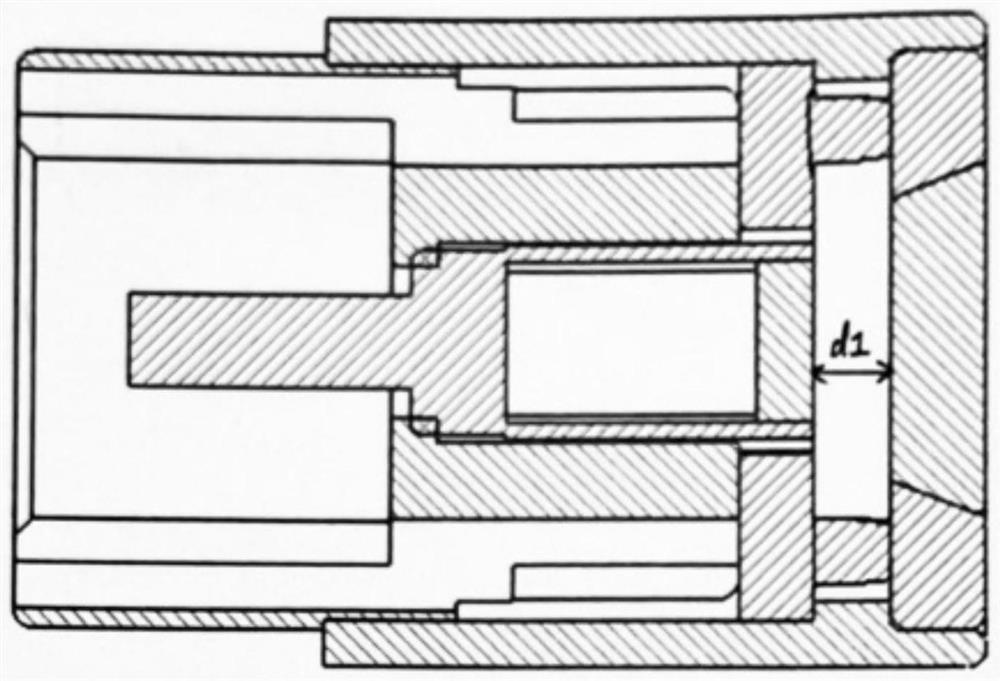
[0066] See figure 2 As shown, the first embodiment provided by the present invention includes: a first lens assembly 12 and a second lens assembly 11 surrounding the outer edge of the first lens assembly 12, wherein the first lens assembly 12 and the second lens assembly 11 are There is an opaque layer in the room. It also includes: a light source assembly 2 and an image sensor 3 , wherein the light source assembly 2 abuts against the second lens assembly 11 and there is a first distance d1 between the image sensor 3 and the first lens assembly 12 .

[0067] Further, as a preferred embodiment, the image sensor 3 is a photoelectric conversion electronic element.

[0068] Further, as a preferred embodiment, the image sensor 3 is a cmos sensor, a ccd element, and the like.

[0069] Further, as a preferred embodiment, the observation distance of the image sensor 3 is preferably 5 cm.

[0070] Further, as a preferred embodiment, the image sensor 3 is disposed coaxially with the...

no. 2 example

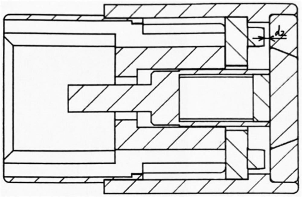
[0077] See image 3 As shown, the second embodiment provided by the present invention includes: a first lens assembly 12 and a second lens assembly 11 surrounding the outer edge of the first lens assembly 12, wherein the first lens assembly 12 and the second lens assembly 11 There is an opaque layer in the room. It also includes: a light source assembly 2 and an image sensor 3 , wherein the image sensor 3 is against the first lens assembly 12 and there is a second distance d2 between the light source assembly 2 and the second lens assembly 11 .

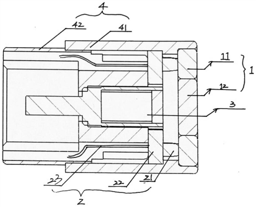
[0078] Further, as a preferred embodiment, the light source assembly 2 includes: a light source 21 , a circuit board 22 for setting and managing the light source 21 , and a cable 23 for supplying power to the light source 21 .

[0079] Further, as a preferred embodiment, the light source 21 is an LED lamp.

[0080] Further, as a preferred embodiment, it further includes: a casing 4, the casing 4 includes an outer casing 41 and an in...

no. 3 example

[0088] In the third embodiment provided by the present invention, a light-blocking or light-absorbing opaque coating is provided between the first lens assembly 12 and the second lens assembly 11 . The opaque coating is an opaque paint or a spray paint with a light blocking effect.

[0089] Further, as a preferred embodiment, the opaque coating can be black polymer waterproof coating, nanocomposite ceramic coating, black water-based glass paint, glass flake coating or other materials with the same effect.


PUM


Abstract

The invention discloses an endoscope lens structure capable of reducing optical signal interference, which comprises a first lens assembly and a second lens assembly at least partially arranged on the outer edge of the first lens assembly, and a light-proof layer is arranged between the first lens assembly and the second lens assembly; and a light source assembly and an image sensor, the light source assembly abuts against the second lens assembly, and a first distance d1 is formed between the image sensor and the first lens assembly, or the image sensor abuts against the first lens assembly, and a second distance d2 is formed between the light source assembly and the second lens assembly, or the image sensor abuts against the first lens assembly, and the light source assembly abuts against the second lens assembly. According to the invention, the light source and the image sensor respectively realize the functions of illumination and image receiving through the independent lenses with the light-proof layers, so that the interference of the light source on optical signals of the image sensor is effectively avoided, and the good and stable imaging quality of the image sensor is ensured.

Description

Technical field [0001] The present invention relates to the technical field of endoscopes, and in particular, to an endoscope lens structure that reduces optical signal interference. Background technique [0002] The existing endoscope lens light source and image sensor achieve illumination and image reception through the same lens. The light source will interfere with the optical signal of the image sensor and affect the imaging quality of the image sensor. Contents of the invention [0003] In view of this, the object of the present invention is to provide an endoscope lens structure that reduces optical signal interference. [0004] In order to achieve the above objects, the technical solutions adopted by the present invention are: [0005] An endoscope lens structure that reduces optical signal interference, including: [0006] A first lens component and a second lens component at least partially disposed on the outer edge of the first lens component, wherein an opaq...

Claims


Application Information

Patent Timeline
Patent Type & Authority Applications(China)
IPC IPC(8): G02B23/24A61B1/06A61B1/04A61B1/00
CPCG02B23/243G02B23/2461G02B23/2484A61B1/04A61B1/0661A61B1/00071A61B1/00163
Inventor 迪特·舒尔茨樊玉娇石伟芊黄延平李佳楠
Owner VITAVIEW MEDTECH (ZHEJIANG) CO LTD
Learn More