
Optical element, camera module and terminal

A technology of camera modules and optical components, applied in the direction of optical components, optical, electrical components, etc., can solve the problems of unavoidable assembly tolerances and insufficient imaging, and achieve clear final imaging, clear shooting imaging, and fine focusing Effect

Pending Publication Date: 2022-07-19
NANCHANG O FILM OPTICAL ELECTRONICS TECH CO LTD
View PDF0 Cites 0 Cited by
  • Summary
  • Abstract
  • Description
  • Claims
  • Application Information

AI Technical Summary

Problems solved by technology

However, due to the limitation of the assembly process level of the camera device, the assembly tolerance is unavoidable. Therefore, when the camera device is used for imaging, the imaging surface cannot be on a plane, resulting in insufficient clarity of the image.

Method used


Image

  • Optical element, camera module and terminal
  • Optical element, camera module and terminal
  • Optical element, camera module and terminal

Examples


Embodiment Construction

[0057] The technical solutions in the embodiments of the present invention will be clearly and completely described below with reference to the accompanying drawings in the embodiments of the present invention. Obviously, the described embodiments are only a part of the embodiments of the present invention, but not all of the embodiments. Based on the embodiments of the present invention, all other embodiments obtained by those of ordinary skill in the art without creative efforts shall fall within the protection scope of the present invention.

[0058] In the present invention, the terms "upper", "lower", "left", "right", "front", "rear", "top", "bottom", "inner", "outer", "middle", The orientation or positional relationship indicated by "vertical", "horizontal", "horizontal", "longitudinal", etc. is based on the orientation or positional relationship shown in the drawings. These terms are primarily used to better describe the invention and its embodiments, and are not intend...


PUM


Abstract

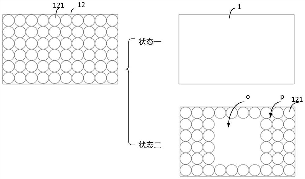
The invention provides an optical element. The optical element comprises a power-on substrate and a plurality of piezoelectric film pieces, when the electrifying substrate is electrified, each piezoelectric film piece can be deformed under the action of voltage to form a plurality of deformation structures, so that the focal length of the optical element is changed, namely, the focal length is changed by changing the curvature or form of the plurality of deformation structures, so that local position focusing is realized; according to the optical element, local fine adjustment is realized through the deformation structure after automatic focusing of the lens, so that fine focusing is realized, and shooting imaging of a camera module or a terminal provided with the optical element is clear. Besides, the terminal provided by the embodiment of the invention comprises the camera module, and the camera module comprises the lens capable of automatically focusing and the optical element capable of locally focusing, so that fine focusing can be realized, and the final image is relatively clear.

Description

technical field [0001] The invention relates to the field of camera equipment, in particular to an optical element, a camera module and a terminal. Background technique [0002] In order to realize that the imaging effect of the imaging device is relatively clear and can adapt to the requirements of shooting scenes of different distances, it is necessary to focus the imaging device when taking pictures. Focusing, also known as focusing and focusing, is a process of changing the distance and distance of the object through the focusing mechanism to make the image of the object clear. Generally, the camera device has multiple focusing methods, namely auto focus, manual focus and multiple focus methods. Generally speaking, camera equipment adopts AF (Automatic Focus, automatic focus) focusing to realize the automatic focusing process to obtain clear images. However, due to the limitation of the assembly process level of the camera device, the assembly tolerance is unavoidable....

Claims


Application Information

Patent Timeline
IPC IPC(8): H04N5/225G02B26/08G03B13/36G03B30/00
CPCG02B26/0875G03B13/36H04N23/55
Inventor 帅文华
Owner NANCHANG O FILM OPTICAL ELECTRONICS TECH CO LTD
Learn More