Infrared ultrafast laser stainless steel surface gray scale marking system

A stainless steel and infrared super technology, applied in laser welding equipment, welding/welding/cutting items, manufacturing tools, etc., can solve the problems of high roughness of pattern marks, difficult control of overall uniformity, low photon resolution, etc., and achieve consistent Good consistency, high consistency, high resolution effect

Pending Publication Date: 2022-03-22
河北金镭赢圣科技有限公司
View PDF0 Cites 0 Cited by
  • Summary
  • Abstract
  • Description
  • Claims
  • Application Information

AI Technical Summary

Problems solved by technology

The grayscale marking method on the surface of stainless steel mainly uses fiber laser as the core device. The pattern marks produced have high roughness, the particle size is basically at the millimeter level, the grayscale color gamut is small, the resolution is low, and the accuracy is poor.
There are several main reasons. The first is that the highest limit level of the consistent repeating unit of the core device is at the nanosecond level, resulting in low photon resolution, photon inhomogeneity, poor consistency, etc.
The second is for laser grayscale marking on the surface of stainless steel. The mechanism of the existing marking equipment is developed based on chemical methods. The laser beam is applied through thermal melting on the surface material of the object to be marked. Slag, cracks, heat-affected zone and other adverse effects
The third is to control process parameters such as laser beam pulse width, power, defocus, filling method, delay parameters, etc., to produce oxide film marking layers with different thicknesses, but the overall uniformity is difficult to control, and the inconsistency of the effect is obvious

Method used


Image

  • Infrared ultrafast laser stainless steel surface gray scale marking system
  • Infrared ultrafast laser stainless steel surface gray scale marking system
  • Infrared ultrafast laser stainless steel surface gray scale marking system

Examples


Embodiment 1

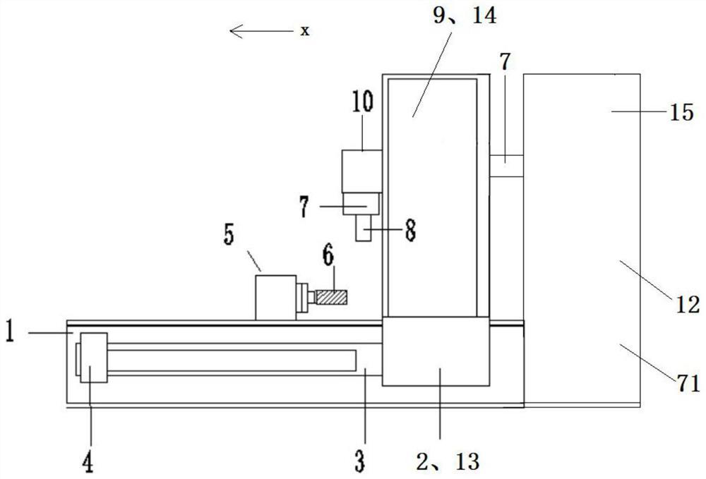
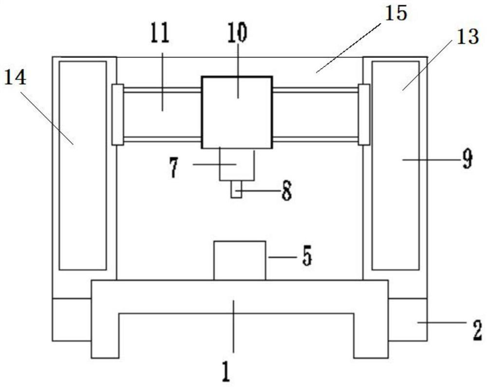
[0049] This embodiment is an example of marking a stainless steel water cup in the infrared ultrafast laser stainless steel surface grayscale marking system of the present invention, and its specific structure is as follows:

[0050] Including a workbench 1 and a laser 71, the laser 71 is an all-solid-state picosecond laser;

[0051] The worktable 1 is provided with an X-axis moving mechanism 13, and the X-axis moving mechanism 13 includes a gantry frame 14 and first slide rails 3 arranged on both sides of the workbench 1; first slide rails 3 on both sides are provided with first The slider 2 and the bottom ends of the two columns 9 of the gantry 14 are respectively connected to the first sliders 2 on both sides, and the two sides of the workbench 1 are respectively provided with a first drive 4, and the two first drives 4 are respectively The first slider 2 for driving the corresponding side moves along the corresponding first slide rail 3 to realize the X-axis movement; the ...

Embodiment 2

[0060] It is basically the same as Example 1, the difference is that the marking is done on the stainless steel disc workpiece, and the marking effect can be found in Figure 5 .


PUM


Abstract

The invention provides an infrared ultrafast laser stainless steel surface gray scale marking system. The infrared ultrafast laser stainless steel surface gray scale marking system comprises a workbench, an optical system and a controller. The optical system comprises an infrared ultrafast laser, a light path and a galvanometer marking head, the light path comprises a shaping light path and a light beam transmission light path, and a galvanometer and a field lens are arranged in the laser galvanometer marking head; an X-axis moving mechanism is arranged on the workbench and connected with the laser galvanometer marking head. The driving mechanism is used for driving the laser galvanometer marking head to move in the X-axis direction of the workbench. And a stainless steel fixing module is arranged on the workbench below the laser galvanometer marking head. According to the method, the stainless steel surface does not need to be subjected to special treatment, the gray scale mark with high uniformity and good consistency can be directly marked on the stainless steel surface, and cracks and mixed colors are almost avoided.

Description

technical field [0001] The invention relates to the technical field of laser marking, in particular to an infrared ultrafast laser stainless steel surface grayscale marking system. Background technique [0002] In recent years, laser marking has replaced traditional marking methods in many fields and has become a conventional processing method, and even formed a new industrial standard. There is an increasing market demand for stainless steel applications. The grayscale marking method on the surface of stainless steel mainly uses fiber laser as the core device. The pattern marks produced have high roughness, the particle size is basically at the millimeter level, the grayscale color gamut is small, the resolution is low, and the accuracy is poor. There are several main reasons. The first is that the highest limit level of the consistent repeating unit of the core device is at the nanosecond level, resulting in low photon resolution, photon inhomogeneity, and poor consistenc...

Claims


Application Information

Patent Timeline
IPC IPC(8): B23K26/362B23K26/0622B23K26/70
CPCB23K26/362B23K26/0622B23K26/702B23K2103/05
Inventor 不公告发明人
Owner 河北金镭赢圣科技有限公司
Why Eureka
Try Eureka