Anti-theft nut punching device

A punching device, anti-theft nut technology, applied in the direction of nuts, feeding devices, positioning devices, etc., can solve the problems of inability to automatically nut, nut deformation, large impact force, etc., to facilitate automatic collection, prevent gear damage, reduce impact effect

Pending Publication Date: 2022-07-22
邯郸市固峰紧固件制造有限公司
View PDF1 Cites 3 Cited by
  • Summary
  • Abstract
  • Description
  • Claims
  • Application Information

AI Technical Summary

Problems solved by technology

[0003] In the prior art, for example, the patent number is CN202121645254.0, and the patent name is a patent for an anti-lock nut punching device. For the hole device, first the hydraulic cylinder drives the punching machine down to punch the nut. After the punching is completed, the hydraulic cylinder drives the punching machine to rise, and then the electric push rod is extended to move the electromagnet to the top of the nut. The electromagnet is energized to generate magnetism. The nut is sucked up from the punching groove, and then keeps sucking up, but there are some problems in use, it can punch the nut at one time, but when the nut is punched, if the nut is punched at one time, not only A large impact force is required, and it is easy to cause deformation of the nut, which will affect the quality of the nut, and this device cannot automatically load the nut, which affects work efficiency

Method used


Image

  • Anti-theft nut punching device
  • Anti-theft nut punching device
  • Anti-theft nut punching device

Examples


Embodiment Construction

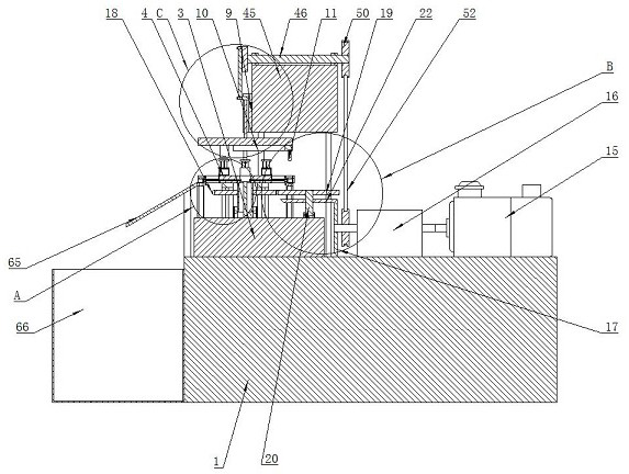
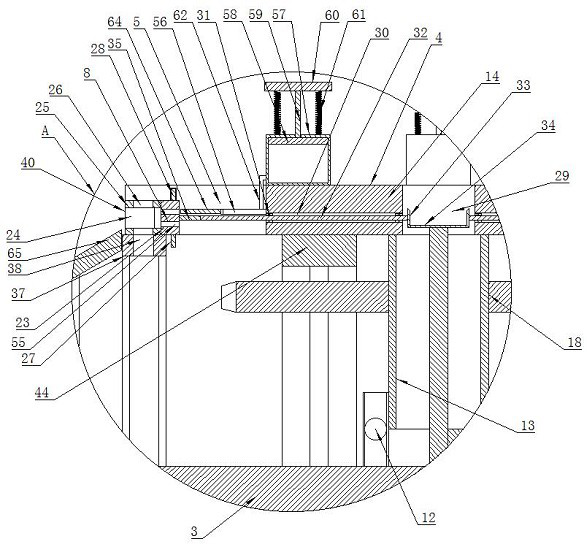
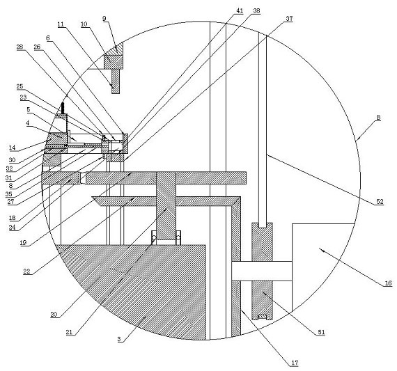
[0030] In order to make the purposes, technical solutions and advantages of the embodiments of the present invention clearer, the technical solutions in the embodiments of the present invention will be clearly and completely described below with reference to the accompanying drawings in the embodiments of the present invention. Obviously, the described embodiments These are some embodiments of the present invention, but not all embodiments. Based on the embodiments of the present invention, all other embodiments obtained by those of ordinary skill in the art without creative efforts shall fall within the protection scope of the present invention.

[0031] In the description of the present invention, it should be understood that the terms "length", "width", "upper", "lower", "front", "rear", "left", "right", "vertical", The orientations or positional relationships indicated by "horizontal", "top", "bottom", "inside", "outside", etc. are based on the orientations or positional r...


PUM


Abstract

The invention discloses an anti-theft nut punching device which comprises a working table, a vibration disc is installed on one side of the upper surface of the working table, a punching table is installed on the upper surface of the working table, a nut overturning mechanism is arranged on the punching table, and a punching mechanism is arranged on the working table. The nut overturning mechanism comprises a containing table which is installed on the punching table and can rotate, a plurality of limiting grooves are formed in the containing table, an annular limiting plate is installed on the punching table, a notch is formed in the annular limiting plate, and a containing frame capable of containing and overturning nuts is installed on the limiting grooves. The punching mechanism comprises a lifting table which is located above the punching table and can move up and down, and a punching upper die is installed at the lower end of the lifting table. The nut punching device has the beneficial effects that nuts can be arranged in order and moved into the limiting groove to be limited through the nut vibration disc, automatic feeding can be achieved, the nuts can be overturned, punching can be conducted on the nuts for multiple times, then the impact force of the punching device can be reduced, and the quality of the nuts is guaranteed.

Description

technical field [0001] The invention relates to the technical field of anti-theft nut processing equipment, and more particularly, to a device for punching anti-theft nuts. Background technique [0002] The anti-theft nut is a product with excellent anti-theft performance in the 21st century. It is mainly used for anti-loosening and anti-theft of the connection and fastening parts of mechanical components. When processing the nut, it is necessary to punch the nut. [0003] In the prior art, for example, the patent number is CN202121645254.0, the patent name is a patent for an anti-lock nut punching device, and its working method is to place the octagonal carbon steel nut to be punched in the punching groove, and then start the punching Hole device, first the hydraulic cylinder drives the punching machine down, punches the nut, after the punching is completed, the hydraulic cylinder drives the punching machine to rise, and then the electric push rod extends, so that the elect...

Claims


Application Information

Patent Timeline
Patent Type & Authority Applications(China)
IPC IPC(8): B21D28/24B21D53/24B21D43/02B21D43/14B21D43/04B21D28/04B21D45/02
CPCB21D28/24B21D53/24B21D43/026B21D43/145B21D43/04B21D28/04B21D45/003B21D45/02
Inventor 高占海
Owner 邯郸市固峰紧固件制造有限公司
Why Eureka
Try Eureka