
Cleaning device for steel structure building

A technology for cleaning devices and buildings, applied in snow traps and other directions, can solve the problems of large energy consumption, weight-heavy steel structure buildings collapse, collapse, etc., and achieve the effect of avoiding excessive resistance

Pending Publication Date: 2022-07-22
山东红三叶钢结构工程有限公司
View PDF0 Cites 0 Cited by
  • Summary
  • Abstract
  • Description
  • Claims
  • Application Information

AI Technical Summary

Problems solved by technology

[0002] Compared with traditional concrete buildings, steel structure buildings have the characteristics of fast construction and easy recycling. Therefore, most factory buildings are constructed with steel structures. The capacity is often poor, so it often only has a one-story structure, and in order to save a certain amount of materials, its top is mostly flat or a structure with a small inclination. It is often necessary to be cleaned by a special person in time, otherwise the snow will be in danger of collapsing after a long period of accumulation, and when cleaning manually, it is not only easy to fall because the snow is easy to slip, but also increases the weight of the steel structure due to the increase in the weight of the cleaning staff. The possibility of the collapse of the building increases the risk, and the traditional method of heating and melting snow in the building not only consumes a lot of energy, but also greatly reduces the snow melting effect when the snow is heavy, highlighting its shortcomings

Method used


Image

  • Cleaning device for steel structure building
  • Cleaning device for steel structure building
  • Cleaning device for steel structure building

Examples


Embodiment Construction

[0018] The present invention will be further elaborated below with reference to the accompanying drawings and specific embodiments.

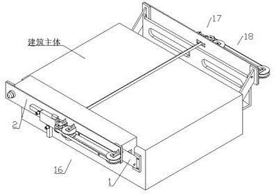
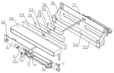
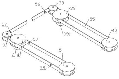
[0019] like Figure 1-6As shown, a cleaning device for a steel structure building includes a front support frame 1, a front support base 2, a No. 1 pulley 3, a No. 2 pulley 4, a No. 3 pulley 5, a front storage box 6, a front brake motor 7, a front push-pull Slot 8, front storage slot 9, No. 1 push rod motor 10, No. 2 push rod motor 11, front push-pull column 12, front column electromagnet 13, front permanent magnet column 14, front identification camera 15, cleaning part 16, auxiliary part 17. The dragging part 18, the left and right parts of the front end of the main body of the building are respectively fixed with a front support frame 1, the front ends of the two front support frames 1 are jointly installed with a horizontal front support seat 2, and the front end of the front support seat 2 is from the left. The horizontal No. 1 pulley 3, N...


PUM


Abstract

The invention discloses a cleaning device for a steel structure building. Comprising a front supporting frame, a front supporting base, a first belt wheel, a second belt wheel, a third belt wheel, a front storage box, a front brake motor, a front push-pull groove, a front storage groove, a first push rod motor, a second push rod motor, a front push-pull column, a front columnar electromagnet, a front permanent magnet column, a front recognition camera, a cleaning part, an auxiliary part and a dragging part. Front supporting frames are fixed to the left portion and the right portion of the front end of the building body respectively, a horizontal front supporting seat is jointly installed at the front ends of the two front supporting frames, and a horizontal first belt wheel, a horizontal second belt wheel and a horizontal third belt wheel are sequentially fixed to the front end of the front supporting seat from left to right. A front brake motor and a rear brake motor are controlled to rotate forwards and backwards at the same time, so that a dragging belt can be dragged forwards and backwards, and then a first push rod motor, a second push rod motor, a third push rod motor and a fourth push rod motor are used for pushing and pulling a first supporting rod, a second supporting rod and a third supporting rod.

Description

technical field [0001] The invention relates to the field of steel structure building cleaning, in particular to a cleaning device for steel structure buildings. Background technique [0002] Compared with traditional concrete buildings, steel structure buildings have the characteristics of fast construction speed and easy recycling. Therefore, the workshops of factories are mostly constructed with steel structures. However, compared with concrete poured buildings, this kind of steel structure buildings has a flat load bearing capacity. The capacity is often poor, so it often has only one layer of structure, and in order to save a certain amount of material, the top of the structure is mostly flat or with a small inclination. When such large-span steel structure buildings encounter heavy snowfall, It often needs to be cleaned in time by a special person, otherwise there is a danger of collapse after a long-term accumulation of snow, and manual cleaning is not only prone to t...

Claims


Application Information

Patent Timeline
Patent Type & Authority Applications(China)
IPC IPC(8): E04D13/10
CPCE04D13/106
Inventor 周新文
Owner 山东红三叶钢结构工程有限公司
Learn More