Low-halo Mini-LED backlight display

A mini-led, display technology, used in instruments, optics, nonlinear optics, etc., to improve the halo phenomenon, reduce or halo phenomenon, reduce the effect of backlight light intensity

Active Publication Date: 2022-07-22
CIVIL AVIATION FLIGHT UNIV OF CHINA
View PDF20 Cites 0 Cited by
  • Summary
  • Abstract
  • Description
  • Claims
  • Application Information

AI Technical Summary

Problems solved by technology

[0004] The present invention intends to propose a new type of display technology, which can solve the technical defects of existing Mini-LED displays

Method used


Image

  • Low-halo Mini-LED backlight display
  • Low-halo Mini-LED backlight display
  • Low-halo Mini-LED backlight display

Examples


Embodiment Construction

[0021] In order to enable those skilled in the art to further understand the present invention, the specific embodiments of the present invention will be described in detail below with reference to the accompanying drawings. It should be noted that the accompanying drawings are for illustrative purposes only, and are not drawn in accordance with the original scale.

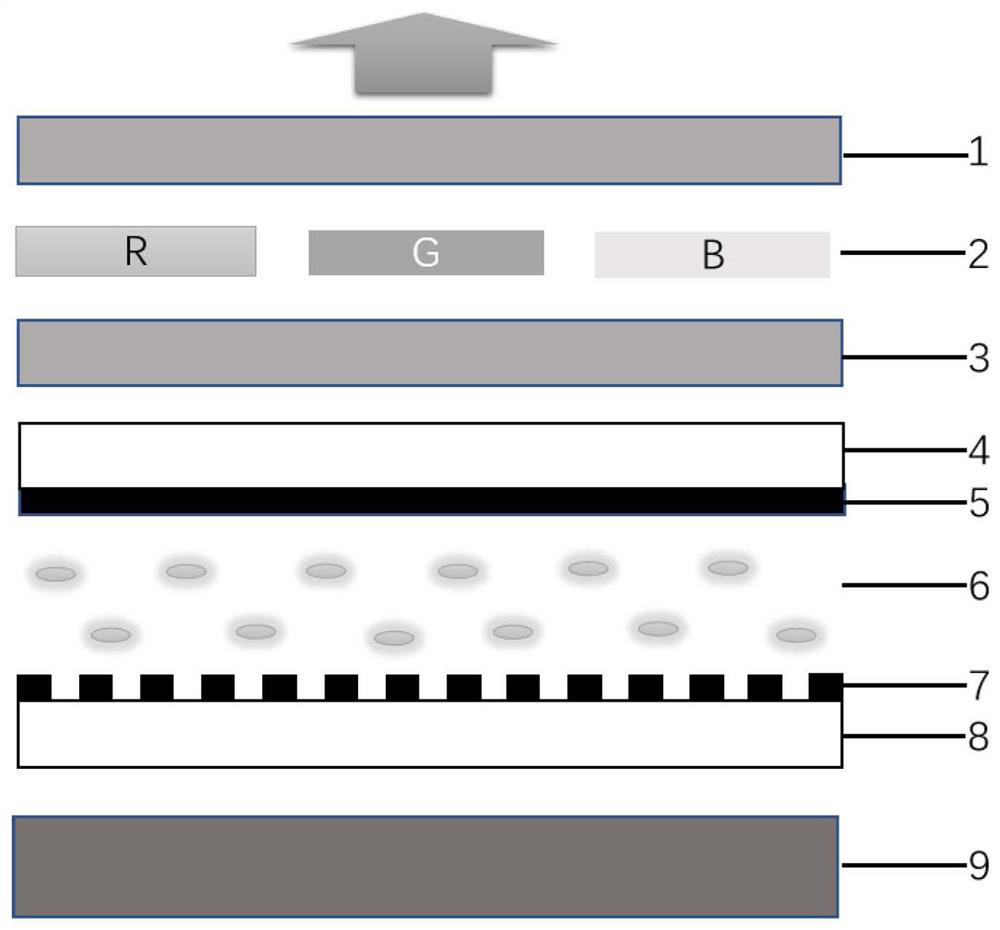
[0022] The schematic diagram of the cross-sectional structure of the present invention is as follows: figure 1 As shown, the structure of the device from top to bottom sequentially includes:

[0023] Upper polarizer 1 , sub-pixels 2 , lower polarizer 3 , upper substrate 4 , common electrode 5 , liquid crystal layer 6 , pixel electrode 7 , lower substrate 8 and Mini-LED backlight layer 9 . The upper polarizer 1 and the lower polarizer 3 are respectively composed of a horizontal polarizer and a vertical polarizer. The order of the two types of polarizers can be adjusted. As long as the angle between the transmissio...


PUM

PropertyMeasurementUnit
thicknessaaaaaaaaaa
thicknessaaaaaaaaaa

Abstract

The invention relates to the field of display, in particular to a low-halo Mini-LED backlight display. The structure of the liquid crystal display sequentially comprises an upper polaroid, a sub-pixel, a lower polaroid, an upper substrate, a common electrode, a liquid crystal layer, a pixel electrode, a lower substrate and a Mini-LED backlight layer from top to bottom. Wherein a plurality of adjacent pixel electrodes are contained in one backlight partition, and the top view of the pixel electrodes in one backlight partition is of a central symmetry structure. The light emitting of each backlight subarea can be controlled in multiple directions through the driving voltage, and the optical effect is equal to the effect of moving the position of the backlight light area to a certain extent. According to the invention, the matching between the display picture and the backlight partition brightness distribution is stronger, the situation that the low-gray-scale display picture corresponds to the high-brightness backlight light intensity is reduced to a certain extent, and the halo phenomenon of the display is reduced.

Description

technical field [0001] The invention relates to the field of display, in particular to a low-halo Mini-LED display capable of modulating the light-emitting direction in a Mini-led backlight partition. Background technique [0002] Mini-LED is another screen lighting technology other than LCD and OLED. Compared with the traditional LED backlight technology, the display with Mini-LED backlight divides the surface light source into independently controlled areas, and then according to the input The image features determine the backlight brightness of each partition, which can not only effectively suppress light leakage, improve the contrast of the display screen, but also greatly reduce power consumption and reduce defects such as afterimages, making the picture more shocking. In addition, the service life of the display can be prolonged, and the production of large-sized display panels is convenient. Generally speaking, the display using Mini-LED backlight combines the high b...

Claims


Application Information

Patent Timeline
Patent Type & Authority Applications(China)
IPC IPC(8): G02F1/13357
CPCG02F1/133612G02F1/133603G02F1/133611
Inventor 窦虎唐深兰王璐李玎任淦羊富彬
Owner CIVIL AVIATION FLIGHT UNIV OF CHINA
Why Eureka
Try Eureka