

Display panel and preparation method thereof
A technology for display panels and array substrates, applied in nonlinear optics, instruments, optics, etc., can solve the problems of high manufacturing costs, achieve the effects of reducing film layer settings, reducing manufacturing costs, and thinning display panels
- Summary
- Abstract
- Description
- Claims
- Application Information
AI Technical Summary
Problems solved by technology
Method used
Image

Examples
Embodiment 1
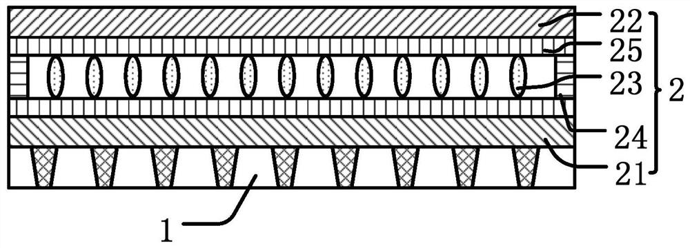
[0040] like figure 1 As shown, this embodiment provides a display panel, including: an anti-peeping structure 1 and a liquid crystal cell 2, the anti-peeping structure 1 is arranged on the lower surface of the liquid crystal cell 2, and the anti-peeping structure 1 is arranged on the The bottom of the above-mentioned liquid crystal box 2 is in order to realize anti-peeping effect.
[0041] The liquid crystal cell 2 includes: an array substrate 21 , a color filter substrate 22 , a liquid crystal layer 23 , a sealant 24 and an electrode layer 25 .
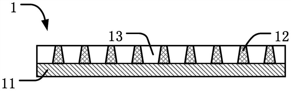
[0042] The glass substrate at the bottom of the array substrate 21 is the glass substrate 11 of the anti-peeping structure 1, that is, the components such as thin film transistors on the array substrate 21 and the film layers such as the black matrix layer 12 are respectively located on the The upper and lower surfaces of the glass substrate 11 .
[0043] The color filter substrate 22 is arranged opposite to the array substrate 21,...
Embodiment 2
[0061] like Figure 4 As shown, this embodiment provides a display panel, including: an anti-peeping structure 1 and a liquid crystal cell 2, the anti-peeping structure 1 is arranged on the lower surface of the liquid crystal cell 2, and the anti-peeping structure 1 is arranged on the The bottom of the above-mentioned liquid crystal box 2 is in order to realize anti-peeping effect.
[0062] The liquid crystal cell 2 includes: an array substrate 21 , a color filter substrate 22 , a liquid crystal layer 23 , a sealant 24 and an electrode layer 25 .
[0063] The glass substrate at the bottom of the array substrate 21 is the glass substrate 11 of the anti-peeping structure 1, that is, the components such as thin film transistors on the array substrate 21 and the film layers such as the black matrix layer 12 are respectively located on the The upper and lower surfaces of the glass substrate 11 .
[0064] The color filter substrate 22 is arranged opposite to the array substrate 21...
Embodiment 3
[0082] like Figure 7 As shown, this embodiment provides a display panel, including: an anti-peeping structure 1 and a liquid crystal cell 2, the anti-peeping structure 1 is arranged on the lower surface of the liquid crystal cell 2, and the anti-peeping structure 1 is arranged on the The bottom of the above-mentioned liquid crystal box 2 is in order to realize anti-peeping effect.
[0083] The liquid crystal cell 2 includes: an array substrate 21 , a color filter substrate 22 , a liquid crystal layer 23 , a sealant 24 and an electrode layer 25 .
[0084]The glass substrate at the bottom of the array substrate 21 is the glass substrate 11 of the anti-peeping structure 1, that is, the components such as thin film transistors on the array substrate 21 and the film layers such as the black matrix layer 12 are respectively located on the The upper and lower surfaces of the glass substrate 11 .
[0085] The color filter substrate 22 is arranged opposite to the array substrate 21,...
PUM
 Abstract
Description
Claims
Application Information