Modeling method, system and equipment of dynamic reactive power compensation device and medium

A technology of compensation device and modeling method, applied in reactive power adjustment/elimination/compensation, AC network to reduce harmonics/ripple, etc., can solve the problem of inability to accurately simulate the operating characteristics of dynamic reactive compensation devices, dynamic reactive power Problems such as low applicability of the compensation device model

Pending Publication Date: 2022-07-22
GUANGZHOU POWER SUPPLY BUREAU GUANGDONG POWER GRID CO LTD +1
View PDF0 Cites 0 Cited by
  • Summary
  • Abstract
  • Description
  • Claims
  • Application Information

AI Technical Summary

Problems solved by technology

[0005] The invention provides a modeling method, system, equipment and medium of a dynamic reactive power compensation device, which solves the problem that the modeling method of the existing dynamic reactive power compensation device is based on a general theoretical model, which cannot be verified without actual operation data. Accurately simulate the actual operating characteristics of the dynamic reactive power compensation device, resulting in the technical problem of low applicability of the generated dynamic reactive power compensation device model

Method used


Image

  • Modeling method, system and equipment of dynamic reactive power compensation device and medium
  • Modeling method, system and equipment of dynamic reactive power compensation device and medium
  • Modeling method, system and equipment of dynamic reactive power compensation device and medium

Examples


Embodiment Construction

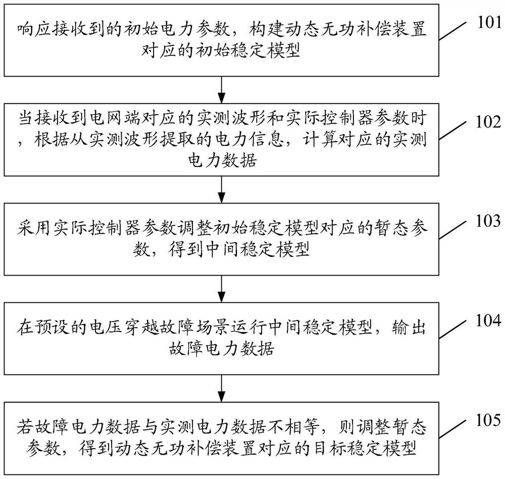
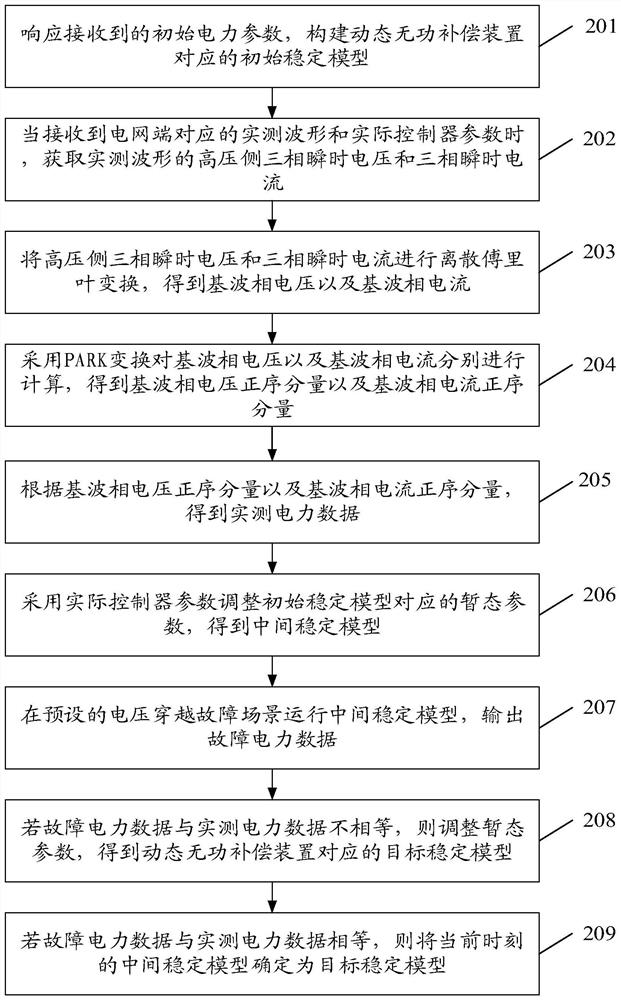
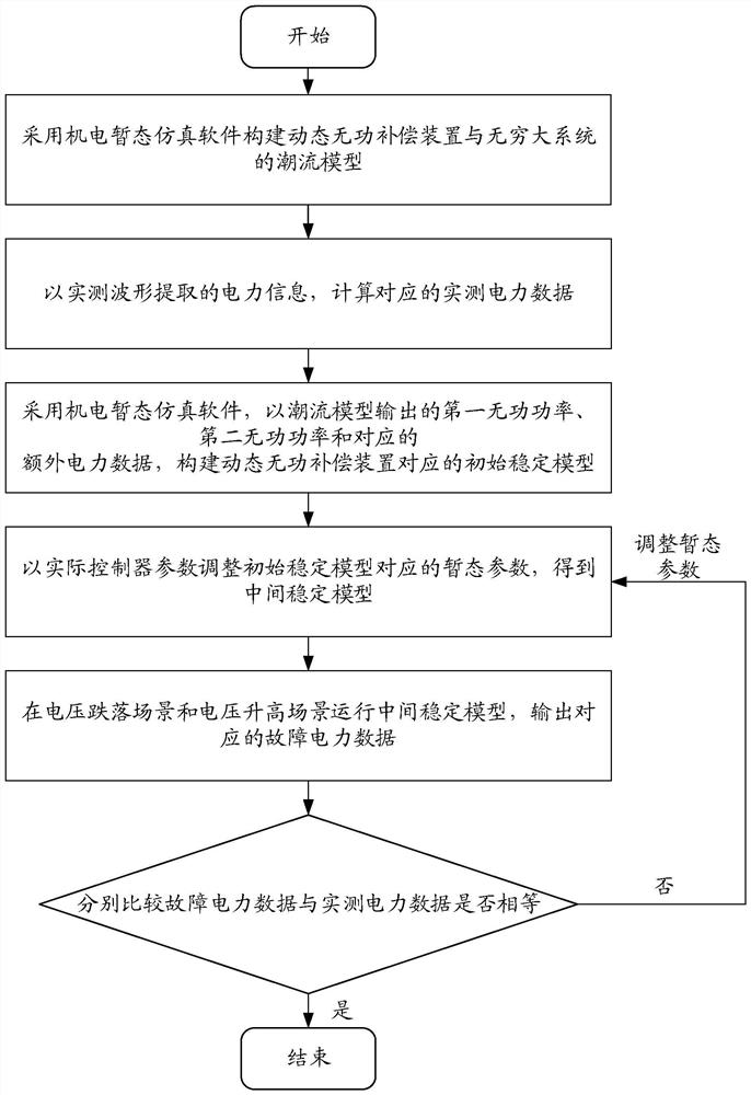
[0054] The embodiments of the present invention provide a modeling method, system, equipment and medium for a dynamic reactive power compensation device, which are used to solve the problem that the modeling method of the existing dynamic reactive power compensation device is based on a general theoretical model and has not undergone actual operation data. It is verified that the actual operating characteristics of the dynamic reactive power compensation device cannot be accurately simulated, resulting in a technical problem of low applicability of the generated dynamic reactive power compensation device model.

[0055] In order to make the purpose, features, and advantages of the present invention more obvious and understandable, the technical solutions in the embodiments of the present invention will be described clearly and completely below with reference to the accompanying drawings in the embodiments of the present invention. Obviously, the following The described embodime...


PUM


Abstract

The invention discloses a modeling method, system and equipment for a dynamic reactive power compensation device and a medium. The modeling method comprises the following steps of: constructing an initial stable model, calculating to obtain actually measured power data according to data corresponding to an actually measured waveform, and adjusting transient parameters of the initial stable model by adopting actual controller parameters to obtain an intermediate stable model; and operating the intermediate stable model in a voltage ride-through fault scene, outputting fault power data, and if the fault power data is not equal to the actually measured power data, adjusting the transient parameters to obtain a target stable model corresponding to the dynamic reactive power compensation device. The technical problems that the modeling mode of the existing dynamic reactive power compensation device is based on a universal theoretical model, verification of actual operation data is not passed, the actual operation characteristics of the dynamic reactive power compensation device cannot be accurately simulated, and the applicability of the generated dynamic reactive power compensation device model is low are solved. A target stable model with high applicability can be constructed according to the actually measured waveform and the actual controller parameters corresponding to the power grid end.

Description

technical field [0001] The present invention relates to the technical field of dynamic reactive power compensation device modeling, and in particular, to a modeling method, system, equipment and medium of a dynamic reactive power compensation device. Background technique [0002] As the problems caused by resources and the environment become more and more prominent, renewable energy technology has received continuous attention and research, which has promoted the rapid development of the new energy power generation industry. The new energy power generation industry mainly includes new energy power plants such as wind farms and photovoltaic power plants. In order to ensure the safe and stable operation of new energy connected to the power system, it is necessary to configure corresponding dynamic reactive power compensation devices in new energy power plants. [0003] Since the voltage ride-through capability of the dynamic reactive power compensation device is of great signi...

Claims


Application Information

Patent Timeline
Patent Type & Authority Applications(China)
IPC IPC(8): H02J3/18H02J3/01
CPCH02J3/18H02J3/01H02J2203/20
Inventor 刘婷胡云李晶黄立滨尚慧玉郭海平陈志聪朱益华赵宏伟李书勇叶萌罗超王历晔曾冠铭苏明章郭天宇
Owner GUANGZHOU POWER SUPPLY BUREAU GUANGDONG POWER GRID CO LTD
Why Eureka
Try Eureka