Printing equipment for printing along peripheral side surface and control method

A technique for printing equipment and a control method, which is applied to printing devices, printing, typewriters, etc., can solve the problems of poor applicability of printing equipment, and achieve the effect of convenient printing

Pending Publication Date: 2022-05-13
东莞市图创智能制造有限公司
View PDF9 Cites 0 Cited by
  • Summary
  • Abstract
  • Description
  • Claims
  • Application Information

AI Technical Summary

Problems solved by technology

[0004] In view of this, the embodiment of the present invention provides a printing device and a control method for printing along the peripheral side to solve the technical problem that some printing devices have low applicability

Method used


Image

  • Printing equipment for printing along peripheral side surface and control method
  • Printing equipment for printing along peripheral side surface and control method
  • Printing equipment for printing along peripheral side surface and control method

Examples


Embodiment 1

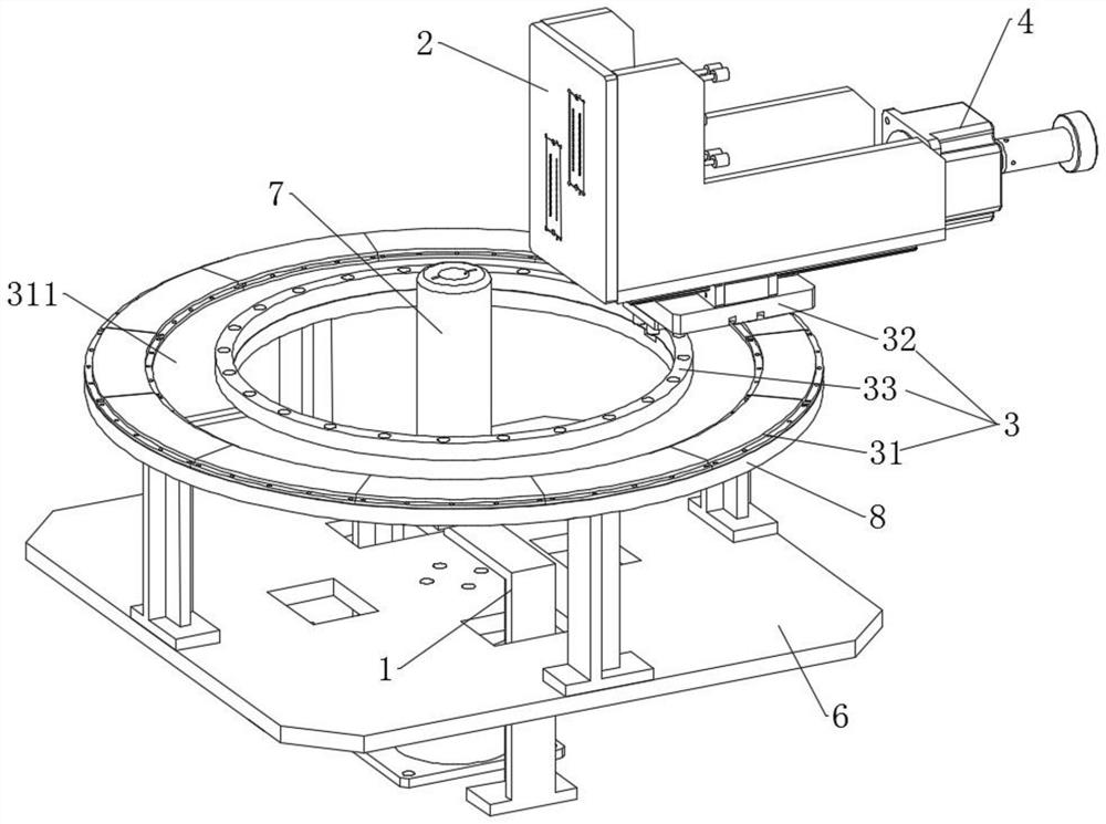
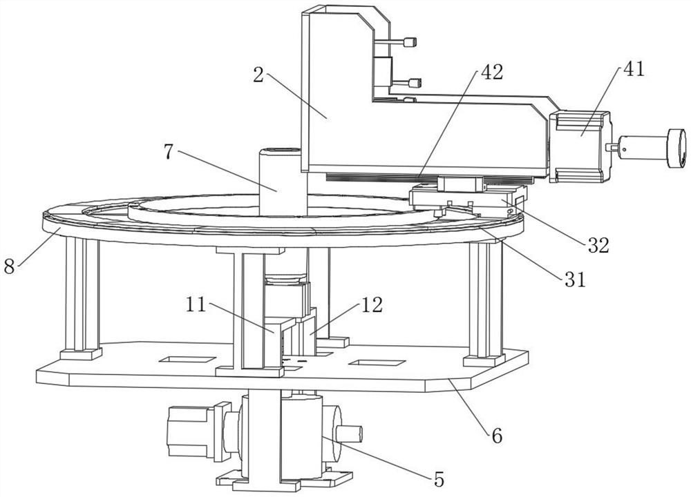
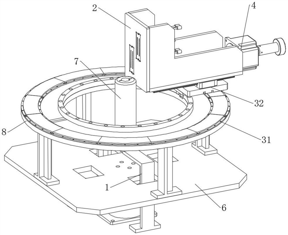
[0045] Embodiment 1 of the present invention provides a printing device for printing along the peripheral side, which is used for printing along the peripheral side of the printing medium. The printing medium can be a cylinder, a cone, a tetrahedron, etc., or a flexible material wrapped around a column Materially, a printing area is formed on the surface of the columnar body, and the printing device is suitable for printing with any proportion of the printing area. combine figure 1 As shown, specifically, the printing device includes:

[0046] Track 8, the printing medium 7 is placed on one side of the track 8, the track 8 can be a circular track 8, or an arc-shaped track 8, specifically, the shape of the track 8 can be determined according to the printing area of ​​the printing medium 7 required to print .

[0047] The printing mechanism 2, the printing mechanism 2 is arranged on the track 8, and is used to spray the liquid in the area to be printed on the to-be-printed med...

Embodiment 2

[0080] Embodiment 2 of the present invention provides a control method for printing along the peripheral side, which is specifically used to control any one of the printing devices in Embodiment 1. Specifically, in combination with Figure 6 , the method includes:

[0081] Obtain the location information of the area to be printed on the printing medium; the area to be printed is on the side of the printing medium 7, which can be on the surrounding side covering the entire printing medium 7, or on a partial area on the side of the printing medium 7. In addition, the printing medium 7 can be a cylinder, a cone or other three-dimensional objects; and the side of the printing medium 7 can be a regular figure or an irregular figure.

[0082] Calculate the movement path of the printing carriage relative to the track according to the position information; pre-store the shape of the track 8 on the system, set a grating on the track 8, read the position of the printing mechanism 2 in t...


PUM


Abstract

The invention belongs to the technical field of printing, solves the technical problem that existing printing equipment is not high in applicability, and provides printing equipment capable of conducting printing along the circumferential side face and a control method. The equipment comprises a track, a printing medium is placed on one side of the track; the printing mechanism is arranged on the track and is used for spraying liquid to a to-be-printed area of a to-be-printed medium according to a preset spraying speed; and the driving mechanism is connected with the printing mechanism, and the driving mechanism is used for driving the printing mechanism to rotate around the peripheral side of the to-be-printed medium along the track. The printing mechanism always correspondingly moves in the range of the printing area regardless of the printing medium with any proportion, so that the printing mechanism does not pass through the non-printing area, printing data of the printing mechanism only needs to be set for the printing area, and printing is facilitated; printing control is facilitated, and the like.

Description

technical field [0001] The invention relates to the technical field of printing, in particular to a printing device and a control method for printing along the peripheral side. Background technique [0002] For printing media such as cylinders that need to be printed in the circumferential direction, the printing media needs to be rotated around its own axis for printing. [0003] Existing cylinder printing usually rotates by clamping one end of the medium to be printed, and prints on the side of the rotating circumference through the printing nozzle. This kind of printing equipment is only suitable for application on the side of the circumference where the printing area surrounds the printing medium. When the printing area occupies only a small part of the circumferential side wall and does not cover the printing medium, the nozzle Most of the orifices that do not emit ink need to be characterized so that the desired pattern can be printed on the print media. But in this ...

Claims


Application Information

Patent Timeline
IPC IPC(8): B41J2/01B41J3/407B41J11/00B41J29/38
CPCB41J2/01B41J3/40733B41J3/40731B41J11/00B41J29/38B41J25/001B41J25/304
Inventor 徐四喜龙武秦杨清华
Owner 东莞市图创智能制造有限公司
Why Eureka
Try Eureka