Riveting machine for riveting binding post of glass lamp cup and riveting method of riveting machine

A technology for riveting glass and glass lamp cups, which is applied in glass production, feeding devices, manufacturing tools, etc., can solve the problems of unstable riveting quality, loose riveting of terminals, and low production efficiency, so as to reduce the rate of defective riveting, The effect of good riveting consistency and improving production efficiency

Active Publication Date: 2022-07-26
佛山市创大为聚氨酯制品有限公司
View PDF10 Cites 1 Cited by
  • Summary
  • Abstract
  • Description
  • Claims
  • Application Information

AI Technical Summary

Problems solved by technology

At present, the existing riveting machines for riveting the terminals of glass lamp cups often have some disadvantages: manually operate the handle of the riveting machine to rivet the terminals, because the material of the glass lamp cup is glass, and the glass lamp cup There are dimensional errors in the thickness of the bottom of the cup. Different glass lamp cups often have different thicknesses at the bottom of the cup. If the riveting terminal is riveted by a manual riveting machine, the quality of the riveting is often not stable enough, and the riveting pressure is too small to easily cause the riveting of the terminal to be not tight. , If the riveting pressure is too high, it will easily cause the glass lamp cup to break, so the riveting consistency is poor, the riveting defect rate is high, and the production efficiency is not high

Method used


Image

  • Riveting machine for riveting binding post of glass lamp cup and riveting method of riveting machine
  • Riveting machine for riveting binding post of glass lamp cup and riveting method of riveting machine
  • Riveting machine for riveting binding post of glass lamp cup and riveting method of riveting machine

Examples


Embodiment Construction

[0051] The technical solutions in the embodiments of the present invention will be clearly and completely described below with reference to the accompanying drawings of the present invention. Obviously, the described embodiments are only a part of the embodiments of the present invention, rather than all the embodiments. Based on the embodiments of the present invention, all other embodiments obtained by those of ordinary skill in the art without creative efforts shall fall within the protection scope of the present invention.

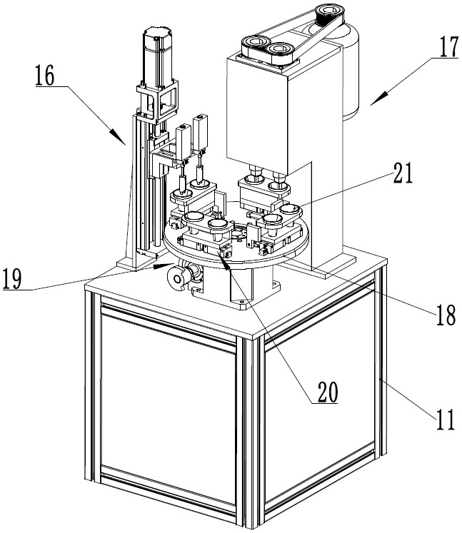
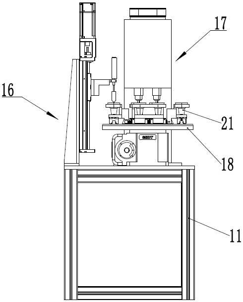
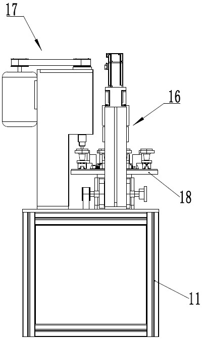
[0052] like Figure 1-4 As shown, the riveting machine for riveting glass lamp cup terminals in this embodiment includes a frame 11 and a control circuit (not shown in the drawings).

[0053] refer to Figure 10 , the frame 11 is provided with a turntable 18 and a turntable drive mechanism 19 . The turntable drive mechanism 19 includes a turntable drive motor 191, a second belt transmission mechanism and a gearbox 195. The gearbox 195 is installed on...


PUM


Abstract

The invention belongs to the technical field of lighting lamp production equipment, and discloses a riveting machine for riveting binding posts of glass lamp cups and a riveting method thereof.The riveting machine comprises a rack and a control circuit, a rotatable rotary disc and a rotary disc driving mechanism are arranged on the rack, a plurality of positioning devices for positioning the glass lamp cups are arranged on the rotary disc, and the control circuit is connected with the control circuit. A feeding station, a measuring station, a riveting station and a discharging station are arranged on the machine frame, a height measuring device is arranged at the position of the measuring station on the machine frame, and a riveting device is arranged at the position of the riveting station on the machine frame. According to the riveting machine and the riveting method thereof, before the binding post is riveted, the height of the cup bottom is measured through the height measuring device, measured data are sent to the control circuit, then the control circuit controls the riveting device to rivet the binding post of the glass lamp cup according to the received measured data, riveting is more accurate, riveting consistency is very good, and the riveting efficiency is improved. The riveting quality is improved, the riveting reject ratio is reduced, the automation level is high, and the production efficiency is improved.

Description

technical field [0001] The invention belongs to the technical field of lighting lamp production equipment, and relates to a riveting machine for riveting glass lamp cup terminals and a riveting method thereof. Background technique [0002] The glass lamp cup, with its low cost and excellent high temperature resistance, is widely used in lighting fixtures. The glass lamp cup is provided with a terminal, which is generally riveted to the bottom of the glass lamp cup. At present, the existing riveting machines for riveting glass lamp cup terminals often have some shortcomings: manually operate the push-down handle of the riveting machine to rivete the terminal posts, because the glass lamp cup is made of glass, and the glass lamp cup is There is a dimensional error in the thickness of the bottom of the cup. Different glass lamp cups often have different thickness and size of the bottom of the cup. Manually operated riveting machine is used to riveted the terminal, the riveting...

Claims


Application Information

Patent Timeline
Patent Type & Authority Applications(China)
IPC IPC(8): B21D39/00B21C51/00B21D43/14
CPCB21D39/00B21C51/00B21D43/14Y02P40/57
Inventor 汪国平
Owner 佛山市创大为聚氨酯制品有限公司
Why Eureka
Try Eureka