Riveting machine

A riveting machine and riveting technology, applied in the field of relays, can solve problems such as not being able to meet the production and quality requirements of parts, high labor intensity, unstable product quality, etc., and achieve simple structure, improved safety, and smooth riveting process Effect

Active Publication Date: 2020-11-06
CHANGZHOU COLLEGE OF INFORMATION TECH
View PDF6 Cites 0 Cited by
  • Summary
  • Abstract
  • Description
  • Claims
  • Application Information

AI Technical Summary

Problems solved by technology

Moreover, there are problems such as low production efficiency, high labor intensity, unstable product quality and high production cost in the existing production process of artificial contact riveting
Manual positioning riveting can no longer meet the needs of the existing automated assembly line for the output and quality of parts

Method used


Image

  • Riveting machine
  • Riveting machine
  • Riveting machine

Examples


Embodiment 1

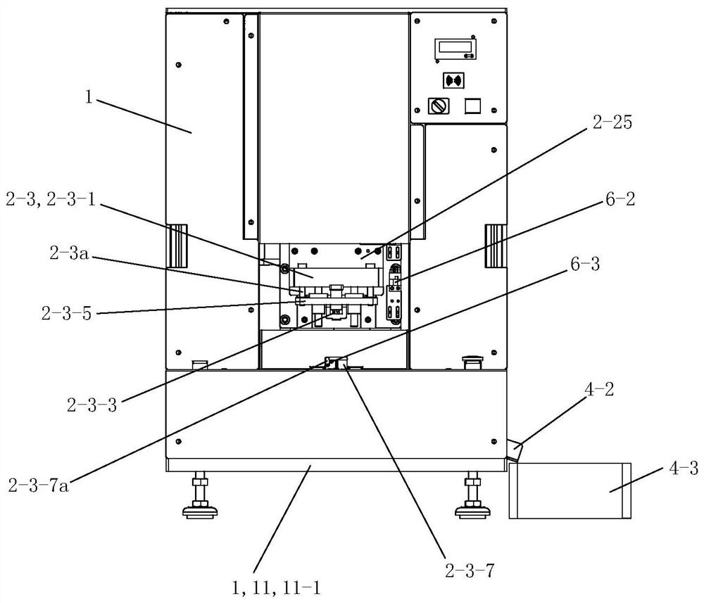
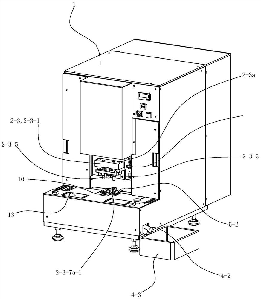
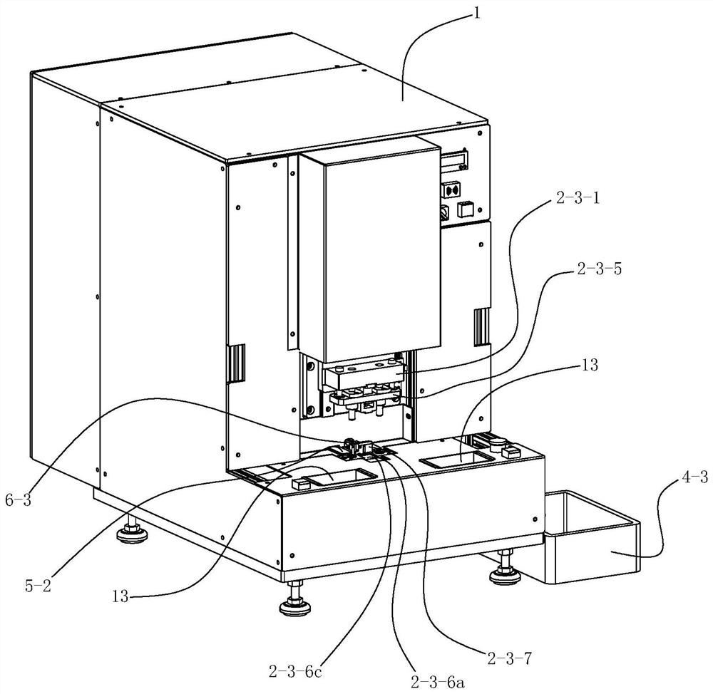
[0073] See Figure 1 to Figure 15 , The riveting machine of the present invention includes a frame 1, a riveting device 2, a blocking device 3, a discharging device 4 and a protection device 5.

[0074] See Figure 1 to Figure 15 , The frame 1 includes a main frame body 11 and an inner frame body 12 . The lower part of the main frame body 11 is provided with an installation base plate 11-1. Corresponding sealing plates are provided around and on the top of the main frame body 11 . The lower part of the inner frame body 12 is provided with a second installation bottom plate 12-1. A support plate 12-2 is respectively provided on the left and right sides of the upper front portion of the second installation base plate 12-1. The inner frame body 12 is fixedly arranged on the upper side of the installation bottom plate 11 - 1 of the main frame body 11 by its second installation bottom plate 12 - 1 , and is located in the main frame body 11 . A raw material box 13 is respective...


PUM


Abstract

The invention discloses a riveting machine which comprises a rack and a riveting device. The riveting device is arranged on the rack and comprises a drive assembly, a transmission assembly, a rivetingassembly and a guiding assembly. The riveting assembly comprises a punch connecting seat, a punch installing seat, steel needle punches, a riveting and guiding assembly, a guiding seat, a riveting seat and a positioning backup plate. The punch connecting seat is fixedly arranged on the transmission assembly. The two steel needle punches are limited and fixedly arranged in the punch installing seat from the upper part through the punch connecting seat. Two riveting holes penetrating through a positioning part of the guiding seat up and down are formed in the positioning part of the guiding seat. A positioning groove corresponding to the positioning part of the guiding seat is formed in the rear part of the middle part of the riveting seat; the positioning groove is provided with two contact placement blind holes for placing relay contacts; and the positions of the two contact placement blind holes correspond to the riveting holes of the positioning part. The drive assembly drives the steel needle punches of the riveting assembly to downwards move along the guiding assembly through the transmission assembly so as to carry out riveting operation.

Description

technical field [0001] The invention relates to the technical field of relays, in particular to a riveting machine for installing relay contacts. Background technique [0002] There are many kinds of switch relays, which are widely used in various switches and play an important role in the conduction of switches. Contacts are one of the most important components of electromagnetic relays. In traditional industries, manual positioning is still used for contact riveting, which is mainly controlled by a foot switch. Workers use tweezers to respectively clamp the two terminals to be riveted to the operating platform. a rivet. In such an operation, the yield rate depends largely on the proficiency of the workers. Moreover, the existing manual contact riveting production process has problems such as low production efficiency, high labor intensity, unstable product quality, and high production cost. Manual positioning riveting can no longer meet the needs of the existing automa...

Claims


Application Information

Patent Timeline
Patent Type & Authority Patents(China)
IPC IPC(8): B21J15/38B21J15/26
CPCB21J15/26B21J15/38
Inventor 潘长江段文拯王文磊朱俊
Owner CHANGZHOU COLLEGE OF INFORMATION TECH
Why Eureka
Try Eureka