Self-adaptive connecting mechanism for sliding block of bending machine and mounting method

A connection mechanism and self-adaptive technology, applied in the field of bending machine, to avoid bearing lateral force and good fitting effect

Active Publication Date: 2022-07-29
湖北工程职业学院(湖北省机械工业学校黄石高级技工学校) +1
View PDF6 Cites 0 Cited by
  • Summary
  • Abstract
  • Description
  • Claims
  • Application Information

AI Technical Summary

Problems solved by technology

[0004] The purpose of the present invention is to provide a self-adaptive connection mechanism for the slider of the bending machine in order to solve the problems existing in the connection mode between the slider and the cylinder of the existing bending machine

Method used


Image

  • Self-adaptive connecting mechanism for sliding block of bending machine and mounting method
  • Self-adaptive connecting mechanism for sliding block of bending machine and mounting method
  • Self-adaptive connecting mechanism for sliding block of bending machine and mounting method

Examples


Embodiment Construction

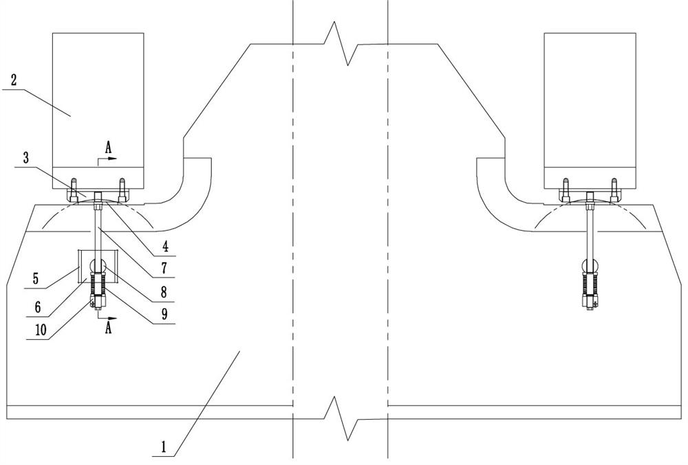
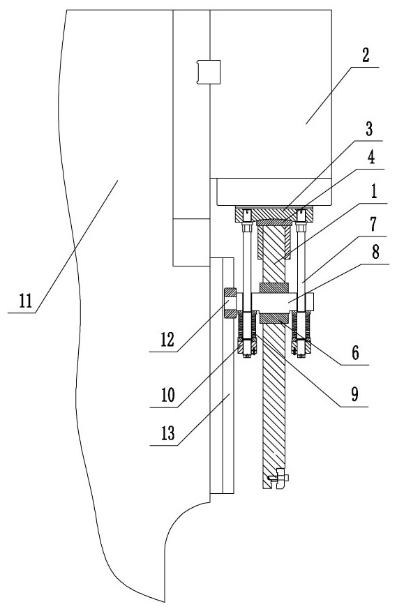
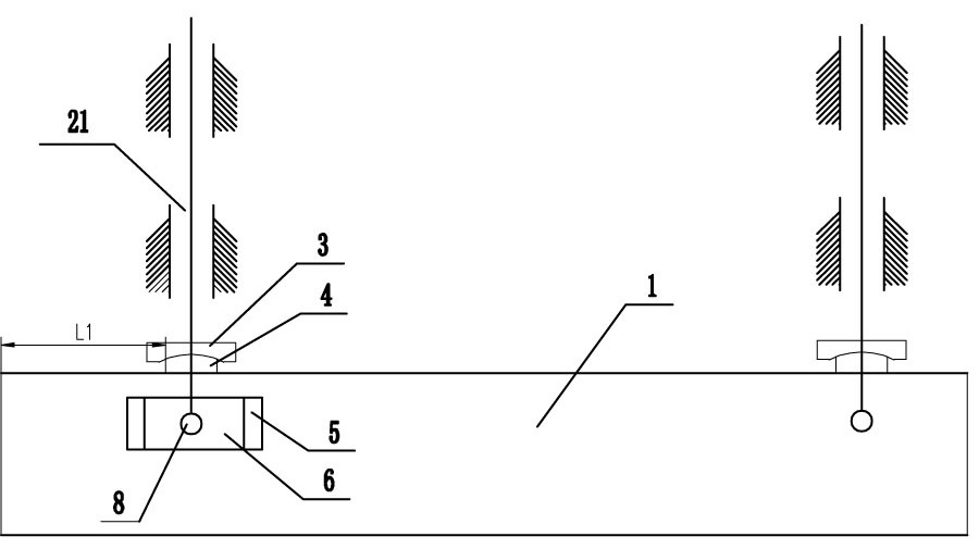
[0018] see Figure 1-2 , this embodiment is an adaptive connection mechanism of a bending machine slider, including a frame 11, a slider 1, an oil cylinder 2 is installed on both sides of the frame 11, and the bottom end of the piston rod 21 of each oil cylinder 2 is fixedly installed There is a concave ball pad 3, the top surface of the slider 1 is equipped with a convex ball pad 4 corresponding to the concave ball pad 3, the convex ball pad 4 cooperates with the concave ball pad 3, and the slider 1 is located directly below the two oil cylinders 2. A pin 8 is installed, each pin 8 runs through the slider 1, and a double-ended screw 7 is installed on both sides of the pin 8. The upper end of the double-ended screw 7 passes through the pin 8 and is connected with the corresponding concave ball pad. 3 is connected, the lower end of the double-ended screw 7 is equipped with a nut 10, the bottom surface of the convex ball washer 4 is slidably connected with the top surface of the...


PUM


Abstract

The invention relates to a self-adaptive connecting mechanism for a sliding block of a bending machine, which comprises a rack and the sliding block, an oil cylinder is arranged on each of two sides of the rack, a concave ball pad is fixedly arranged at the bottom end of a piston rod of each oil cylinder, a convex ball pad is arranged on the top surface of the sliding block and corresponds to the concave ball pad, the convex ball pad is matched with the concave ball pad, a pin shaft is arranged on the sliding block and is positioned under the two oil cylinders, and the pin shaft is matched with the concave ball pad. Each pin shaft penetrates through the sliding block, the two sides of each pin shaft are each provided with a double-thread screw, the upper ends of the double-thread screws penetrate through the pin shafts and are connected with the corresponding concave ball pads, the bottom faces of the convex ball pads are in sliding connection with the top faces of the sliding blocks, a sliding groove is formed in the position, located on one pin shaft, of each sliding block, a sliding base is installed in each sliding groove, and the sliding bases horizontally move along the sliding grooves. A pin shaft at the sliding chute penetrates through the sliding seat and is rotationally connected with the sliding seat; a vertical linear track is arranged on each of the positions, corresponding to the pin shafts on the two sides, of the rack, a guide wheel is installed at the end, facing the rack, of each pin shaft, and the guide wheels move along the corresponding linear tracks; the oil cylinder is prevented from being damaged, and installation is more convenient.

Description

technical field [0001] The invention relates to the field of bending machines, in particular to an adaptive connecting mechanism for a sliding block of a bending machine. Background technique [0002] At present, most of the bending machines on the market are two sets of cylinder-driven sliders with a downward structure. There are two main ways to connect the slider and the piston rod of the cylinder: one is to open a small square window on both sides of the slider corresponding to the lower part of the piston rod, and use the screw to connect directly and rigidly. , it is easy to cause the piston rod to tilt laterally during operation, thereby damaging the inner wall of the cylinder, and in more serious cases, it will cause the connecting screw to break and the slider to fall off, which has a great potential safety hazard; [0003] In another way, a concave-convex ball washer is installed between the piston rod and the slider, and a screw with a disc spring is installed at...

Claims


Application Information

Patent Timeline
Patent Type & Authority Applications(China)
IPC IPC(8): B21D7/06
CPCB21D7/06
Inventor 李新梅黄鹏李俊华周红祥胡启迪
Owner 湖北工程职业学院(湖北省机械工业学校黄石高级技工学校)
Why Eureka
Try Eureka