Steel wire straightening machine

A straightening machine and steel wire technology, applied in the field of steel wire processing, can solve problems such as unfavorable straightening process, and achieve the effect of avoiding lateral bending

Active Publication Date: 2022-07-29
江苏通工金属科技有限公司
View PDF9 Cites 4 Cited by
  • Summary
  • Abstract
  • Description
  • Claims
  • Application Information

AI Technical Summary

Problems solved by technology

[0003] In the above-mentioned prior art, the position of the reel is fixed during unwinding, and the steel wires are arranged from one end of the reel to the other end, and the fixed position of the reel during unwinding will cause lateral bending of the steel wire when it enters the correction mechanism. In the subsequent correction, it is necessary to correct the bending caused by the steel wire entering the correction mechanism, which is not conducive to the correction process

Method used


Image

  • Steel wire straightening machine
  • Steel wire straightening machine
  • Steel wire straightening machine

Examples


Embodiment

[0022] see Figure 1 to Figure 3 , the present invention provides a kind of technical scheme:

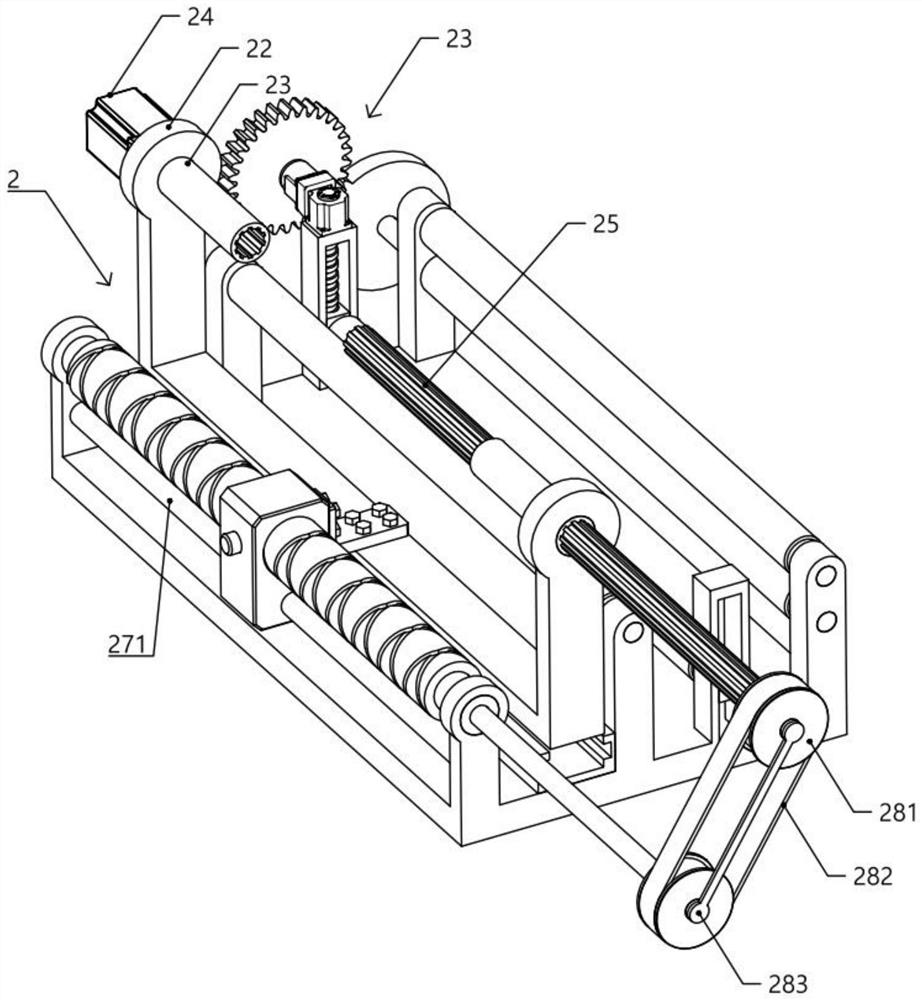
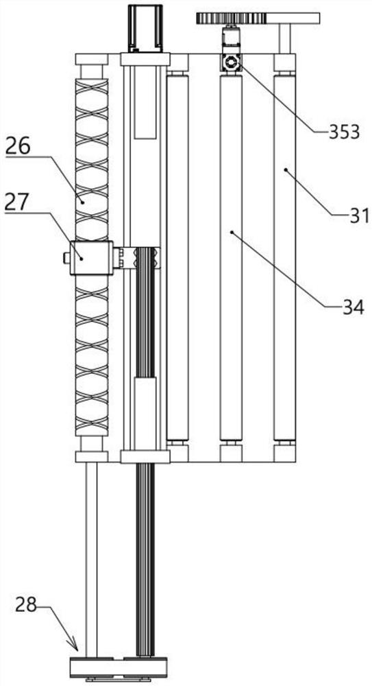
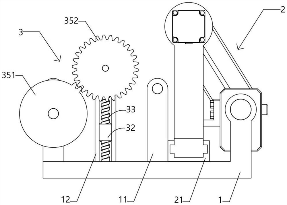
[0023] A steel wire straightening machine, comprising a base plate 1, an unwinding mechanism 2 and an adaptive straightening mechanism 3, wherein:

[0024] The four uprights 11 are arranged on two sides of the base plate 1 in pairs, wherein the two uprights 11 on different sides are oppositely arranged, and a vertical guide slot 12 is provided between the two uprights 11 on the same side;

[0025] The unwinding mechanism 2 includes a linear guide 21, a rewinding frame 22, a sleeve 23, a motor 24, a spline shaft 25, a double helical guide rod 26, a crescent plate 27 and a transmission assembly 28. The linear guide 21 is arranged on the bottom plate 1. The reel frame 22 is fitted in the guide rail 21 and forms a moving pair in the guide rail 21. The two sleeves 23 are rotatably installed on both sides of the reel frame 22. The power output end of the motor 24 is connected, the splin...


PUM


Abstract

The steel wire straightening machine comprises a bottom plate, an unwinding mechanism and a self-adaptive straightening mechanism, the unwinding mechanism comprises a linear guide rail, a winding frame, a sleeve, a motor, a spline shaft, a double-helix guide rod, a crescent plate and a transmission assembly, the linear guide rail is arranged on the bottom plate, and the winding frame is installed in the guide rail in a matched mode; the self-adaptive straightening mechanism comprises a rubber roller, a sliding block, a lead screw, a lower pressing rod and an intermittent transmission assembly. When a steel wire coil is unwound through the unwinding mechanism, the spline shaft rotates along with the unwinding mechanism and drives the double-helix guide rod to rotate through the transmission assembly, finally, the crescent plate translates in a reciprocating mode along the double-helix guide rod, the winding frame translates along with the crescent plate, and therefore lateral bending force cannot be generated when the steel wire enters the self-adaptive straightening mechanism in the unwinding process; and the self-adaptive straightening mechanism drives a lower pressing rod to vertically translate according to the contact between the conveyed steel wire and a rubber roller, so that the self-adaptive straightening mechanism can apply straightening force according to the bending degree of the steel wire in a self-adaptive manner.

Description

technical field [0001] The invention relates to the technical field of steel wire processing, in particular to a steel wire straightening machine. Background technique [0002] Publication number CN210333819U provides a wire pay-off device with straightening function, including a feeding assembly, a pay-off seat, a straightening assembly, and a pressing wheel assembly. The number of feeding assemblies is two and is symmetrically fixed on the front and rear of the base. On the side, the feeding component includes a feeding seat, a feeding rod, a movable rod, a threaded seat, a screw, and a feeding motor. The number of pay-off seats is two and is symmetrically fixed on the front and rear sides of the base, and the pay-off seat is fixed on the base. , the pay-off seat has an L-shaped structure, the pay-off seat is provided with a pay-off slot, and the pay-off groove is in a U-shaped structure. The straightening component is located on the left side of the pay-off seat. Driving...

Claims


Application Information

Patent Timeline
Patent Type & Authority Applications(China)
IPC IPC(8): B21F1/02B21F23/00B21C47/18B21C47/28
CPCB21F1/02B21F23/00B21C47/18B21C47/28Y02P70/10
Inventor 韩磊
Owner 江苏通工金属科技有限公司
Why Eureka
Try Eureka