Circular filter cloth cutting device

A filter cloth and cutting technology, which is applied in metal processing and other directions, can solve problems such as deformation and lack of fixing of filter cloth, and achieve the effect of complete cutting, convenient collection, and good quality

Pending Publication Date: 2022-07-29
江苏速莱尔环保科技有限公司
View PDF5 Cites 0 Cited by
  • Summary
  • Abstract
  • Description
  • Claims
  • Application Information

AI Technical Summary

Problems solved by technology

[0007] The purpose of the present invention is to provide a circular filter cloth cutting device to solve the lack of fixing of the filter cloth during cutting proposed in the above background technology, which may easily lead to deformation during cutting; Issues related to cropping

Method used


Image

  • Circular filter cloth cutting device
  • Circular filter cloth cutting device
  • Circular filter cloth cutting device

Examples


Embodiment 1

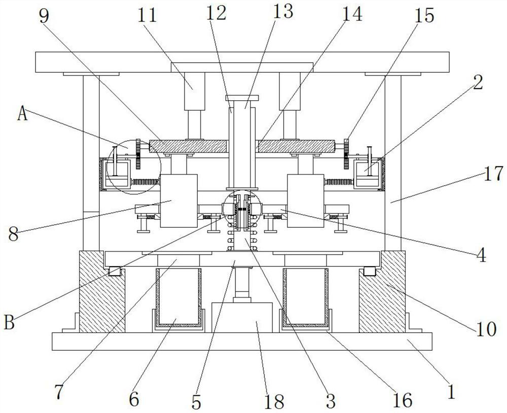
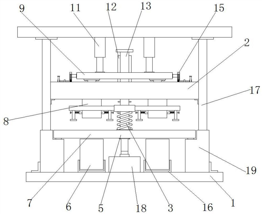
[0046] Example 1, as figure 1 , 2 As shown in , 4 and 5, the circular hollow knife 8 will gradually pass through the interior of the through groove 402 when moving. At this time, the circular hollow knife 8 will be in contact with the two groups of contact heads 403. Because the elastic force of the two groups of third springs 404 is greater than The elastic forces of the two sets of second springs 307 and the first springs 304 make the circular hollow knife 8 push the two sets of contact heads 403 together to drive the connecting plates 401 to move downward together, and the two sets of connecting plates 401 simultaneously drive the collar 303 to move downward. When moving down, the oblique edges of the first teeth 302 and the second teeth 306 slide against each other. When the squeeze rod 405 contacts the filter cloth and squeezes it to a certain extent, the connecting plate 401 cannot continue to move downward. In addition, the first locking teeth 302 and the second lockin...

Embodiment 2

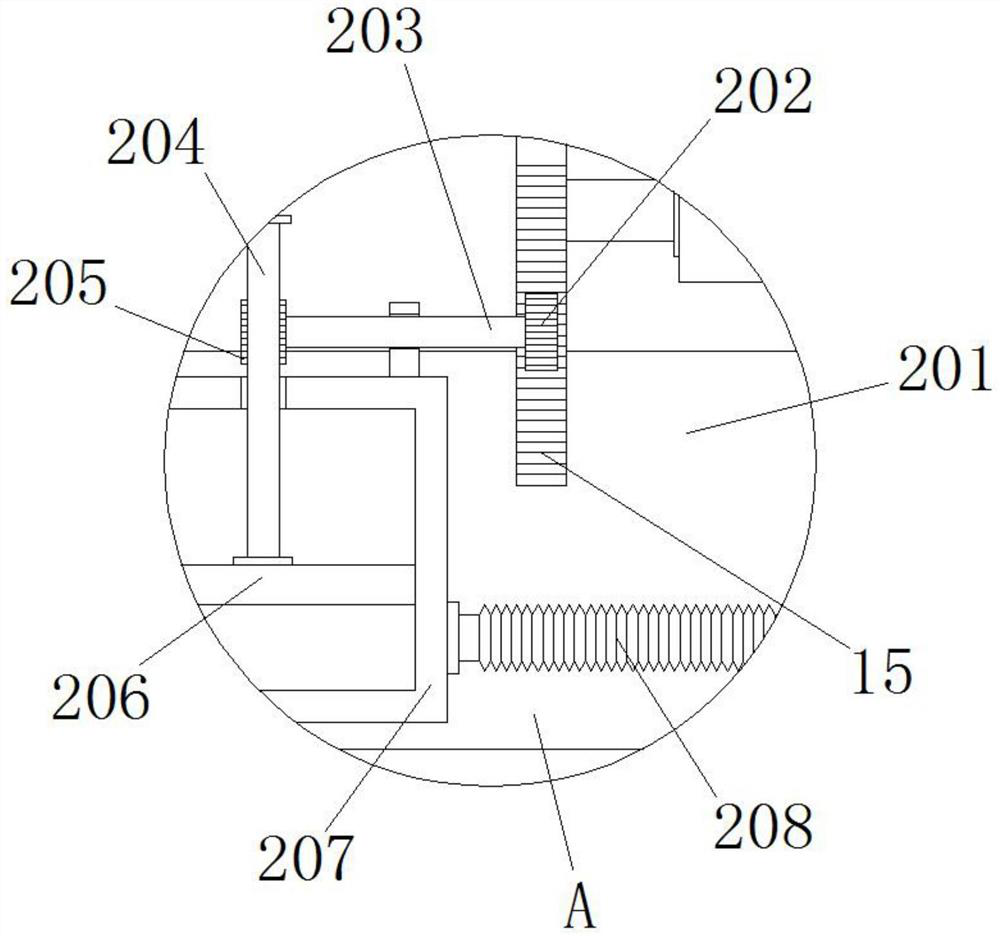
[0047] Example 2, as figure 1 , 2 As shown in and 6, when changing the cutting diameter, the rotary drive motor 18 drives the turntable 5 to rotate, and the turntable 5 drives the limit bar 12 and the slide bar 13 to rotate through the support column 301. Under the cooperation of the limit groove 14, The mounting plate 9 is driven to rotate as a whole, so as to rotate the different through holes 7 and the circular hollow knife 8 to the top of the storage box 6, so as to carry out cutting of different diameters. At the same time, the first rack 15 will rotate with the mounting plate 9, A rack 15 pushes the first gear 202 and the transmission shaft 203 to rotate, and the transmission shaft 203 pushes the entire air cavity 207 to rotate and move inside the annular slide rail 201 .

[0048] Working principle: First, place the filter cloth to be cut above the through hole 7. At this time, the electric push rod 11 drives the entire mounting plate 9 and the hollow hollow knife 8 to ...


PUM


Abstract

The invention discloses a circular filter cloth cutting device which comprises a bottom plate, supporting tables are arranged at the edges of the two sides of the top of the bottom plate, a supporting frame is arranged at the tops of the two supporting tables, two electric push rods are arranged in the middle of the bottom of the supporting frame, and a mounting plate is arranged at the output ends of the two electric push rods. A limiting groove is formed in the middle of the mounting plate, first racks are arranged on the two sides of the mounting plate, and circle center hollow cutters are arranged on the two sides and the two ends of the bottom of the mounting plate. Through cooperation of the clamping assembly and the pressing assembly, when the circle center hollow cutter moves downwards for cutting, the pressing assembly can be driven to move downwards, so that two sets of extrusion rods can firmly press the two sides of the filter cloth, and meanwhile, through cooperation of the clamping assembly, the pressing assembly can be limited and fixed; and it can be guaranteed that the pressing assembly cannot be loosened, the filter cloth is prevented from deviating, cutting is more complete, and the quality is better.

Description

technical field [0001] The invention relates to the technical field of cutting devices, in particular to a circular filter cloth cutting device. Background technique [0002] Filter cloth can generally be divided into qualitative and quantitative two. After the qualitative filter cloth is filtered, more cotton fibers are generated, so it is only suitable for qualitative analysis; the quantitative filter cloth, especially the ashless filter cloth, can resist chemical reactions more effectively after special treatment procedures, so The resulting impurities are few and can be used for quantitative analysis. In addition to the filter cloths used in general laboratories, there are also many applications of filter cloths in life and engineering. Other air filter cloths used to test suspended particles in the air, as well as fiber filter cloths for different industrial applications, etc., need to cut the filter cloth into circular shapes under certain circumstances, and a filter...

Claims


Application Information

Patent Timeline
Patent Type & Authority Applications(China)
IPC IPC(8): B26D1/44B26D7/02B26D7/00B26D7/18B26D7/26
CPCB26D1/445B26D7/025B26D7/00B26D7/1863B26D7/2614B26D2007/0018
Inventor 祁兆生
Owner 江苏速莱尔环保科技有限公司
Why Eureka
Try Eureka