Air control valve with acceleration mitigation function

An air control and relief valve technology, applied in the direction of control valve and air release valve, brake, brake components, etc., can solve the problem of poor relief effect of train acceleration, and achieve the effect of fast inflation, fast gas pressure and good relief effect.

Pending Publication Date: 2022-07-29
CRRC QIQIHAR ROLLING CO LTD
8 Cites 0 Cited by

AI-Extracted Technical Summary

Problems solved by technology

[0005] The invention provides an air control valve with an acceleration relief funct...

Method used

2 and 3, the control valve body 40 has a train passage 60, the air inlet of the train passage 60 is communicated with the train pipe 100, and the air outlet of the train passage 60 is communicated with the train chamber 211. The use of the train channel 60 has the advantage of facilitating the connection between the train pipe 100 and the air outlet of the air chamber 22 , and is beneficial to the miniaturization of the control valve body 40 .
As shown in Fig. 1 and Fig. 2, relief spool 30 also comprises the locking nut 34 that is connected with valve stem 32, and valve stem 32 has annular projection, and bonnet 33 is sandwiched between locking nut 34 and annular Between the protrusions, a lock nut 34 is used to connect the valve cap 33 with the valve stem 32, which has the advantage of simple structure.
As shown in Figure 1 and Figure 2, control valve body 40 has relief passage 50, and the air inlet of relief passage 50 is connected with acceleration relief air cylinder 120, and the air outlet of relief passage 50 is connected with the air intake of inflatable chamber 22 The port is connected, and the relief channel 50 is adopted, which has the advantage of being convenient for connecting the air inlet of the acceleration relief air cylinder 120 and the air charging chamber 22, and is convenient for miniaturization of the control valve body.
As shown in Figure 1 and Figure 2, relief spool 30 comprises valve stem 32 and bonnet 33 that are connected, and plugging member 31 is the plugging spool 311 that is arranged on the first end of valve stem 32, valve The cap 33 separates the drive chamber 21 into a train chamber 211 and a secondary air chamber 212 . The relief valve core 30 with the above structure has the advantage of simple structure.
As shown in Figure 1, check valve 51 comprises check valve core 511 and first back-moving spring 512, and relief two section 53 comprises the reduced diameter section 531 and the expanded diameter section 532 that are connected, and check valve core 511 can It is movably arranged on the enlarged diameter section 532 and corresponds to the air outlet of the reduced diameter section 531 , and the two ends of the first return spring 512 abut against the main valve lower cover 14 and the check valve core 511 respectively. The check valve with the above structure has the advantages of simple structure and easy installation. Moreover, the first reset spring 512 can be used to realize the automatic reset of the non-return valve core.
As shown in Figure 2 and Figure 3, relief valve body 20 comprises relief valve body 23 and cover is located at the relief valve cover 24 of relief valve body 23, and train channel 60 comprises train one section 61 and train two sections 62 connected , the air inlet of the first section 61 of the train is connected with the train pipe 100, the first section 61 of the train is arranged on the control valve body 40 and extends along the horizontal direction, the second section 62 of the train is arranged on the relief valve cover 24, and the air outlet of the second section 62 of the train is connected to the train The cavities 211 communicate with each other. The relief valve body 20 with the above structure has the advantage of being easy to process and assemble.
As shown in Figure 3, control valve body 40 has anti-fill passage 70, and the air inlet of anti-fill passage 70 is communicated with the air outlet of inflatable cavity 22, and the air outlet of anti-fill passage 70 is communicated with train one section 61 . The use of the reverse charging channel 70 has the advantage of being convenient for connecting the train section 61 and the air outlet of the inflation chamber 22 , and is beneficial to the miniaturization of the control valve body 40 .
As shown in Figure 5, control valve body 40 has secondary wind passage 80, and the air inlet of secondary wind passage 80 is communicated with main valve lower cavity 12, and the air outlet of secondary wind passage 80 is connected with secondary wind chamber 212 . Adopting the anti-fill passage 70 has the advantage of being convenient for connecting the main valve lower chamber 12 and the auxiliary air chamber 212 , and is beneficial to the miniaturization of the control valve body 40 .
As shown in Figure 8, piston rod 15, slide valve 16 and slide valve sleeve 17 are arranged in main valve body 10, and piston rod 15 is movably arranged in main valve body 10, and piston rod 15 will main valve body The inner chamber of 10 is divided into the upper chamber 11 of the main valve and the lower chamber 12 of the main valve. The inner side walls are attached together, the other side of the slide valve 16 is embedded in the piston rod 15 , the slide valve sleeve 17 is provided with...

Abstract

The invention provides an air control valve with an accelerating and relieving function, which comprises a main valve body, a main air cylinder, an auxiliary air cylinder, an auxiliary air cylinder, an auxiliary air cylinder, an auxiliary air cylinder, an auxiliary air cylinder, an auxiliary air cylinder, an auxiliary air cylinder, an auxiliary air cylinder, an auxiliary air cylinder and an auxiliary air cylinder, and is characterized in that the main valve body is provided with a main valve upper cavity and a main valve lower cavity which are arranged at an interval; the release valve body is provided with a driving cavity and an air inflation cavity which are arranged at an interval, an air inlet of the air inflation cavity is communicated with the acceleration release air cylinder, and an air outlet of the air inflation cavity is communicated with a train pipe; the release valve element is movably arranged in the driving cavity, the release valve element divides the driving cavity into a train cavity and an auxiliary air cavity, the train cavity is communicated with the train pipe, the auxiliary air cavity is communicated with the main valve lower cavity, and the end of the release valve element is provided with a plugging piece extending into the inflation cavity; the plugging piece is provided with a communicating position for communicating the air outlet and the air inlet of the inflating cavity and a closing position for separating the air outlet and the air inlet of the inflating cavity. By means of the technical scheme, the problem that the train acceleration relieving effect is poor can be solved.

Application Domain

Application and release valves

Technology Topic

EngineeringMechanics +1

Image

  • Air control valve with acceleration mitigation function
  • Air control valve with acceleration mitigation function
  • Air control valve with acceleration mitigation function

Examples

  • Experimental program(1)

Example Embodiment

[0039] The technical solutions in the embodiments of the present invention will be clearly and completely described below with reference to the accompanying drawings in the embodiments of the present invention. Obviously, the described embodiments are only a part of the embodiments of the present invention, but not all of the embodiments. The following description of at least one exemplary embodiment is merely illustrative in nature and is in no way intended to limit the invention, its application, or uses. Based on the embodiments of the present invention, all other embodiments obtained by those of ordinary skill in the art without creative efforts shall fall within the protection scope of the present invention.
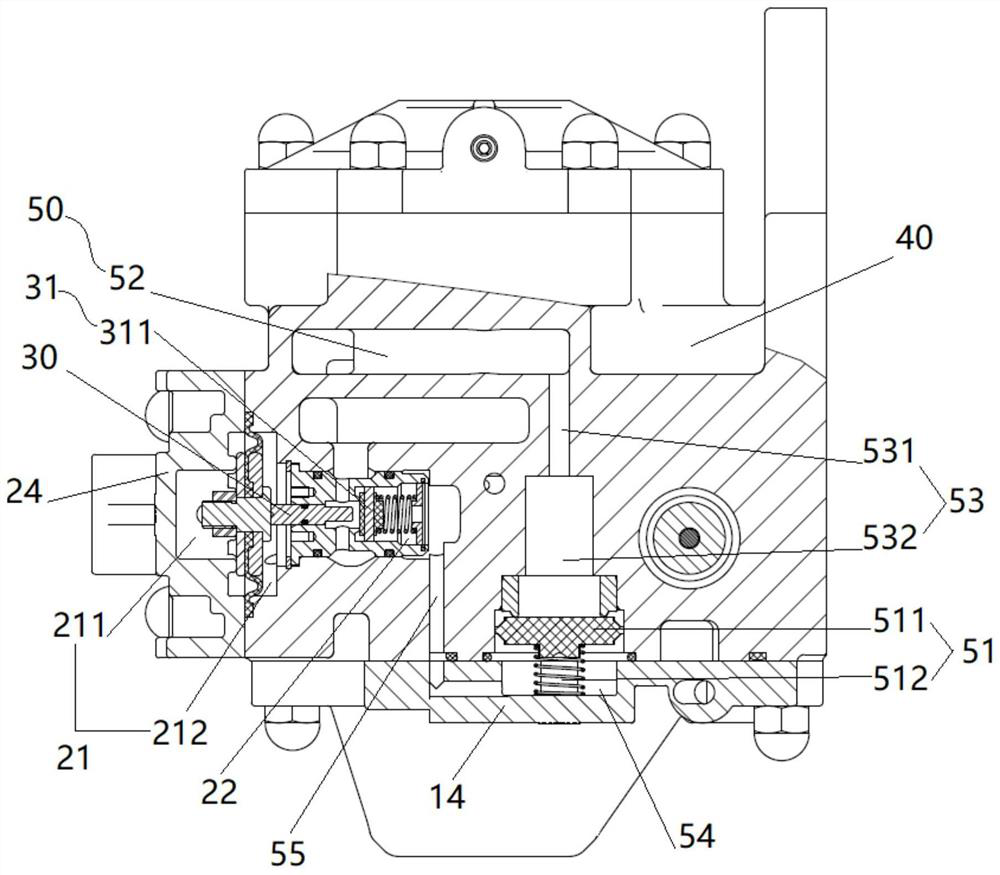
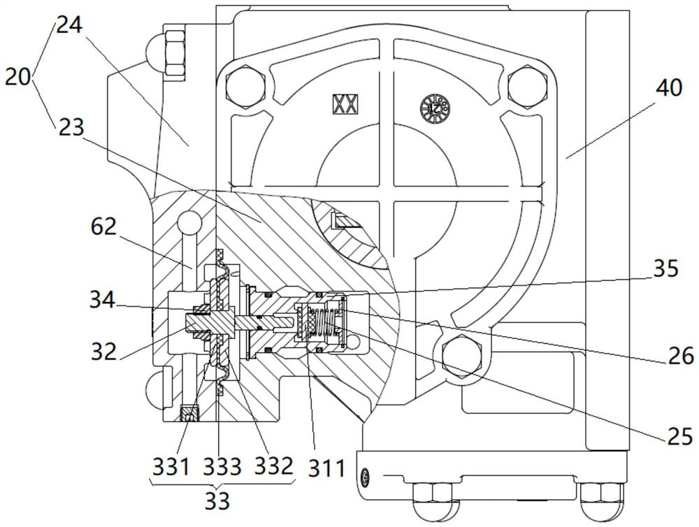
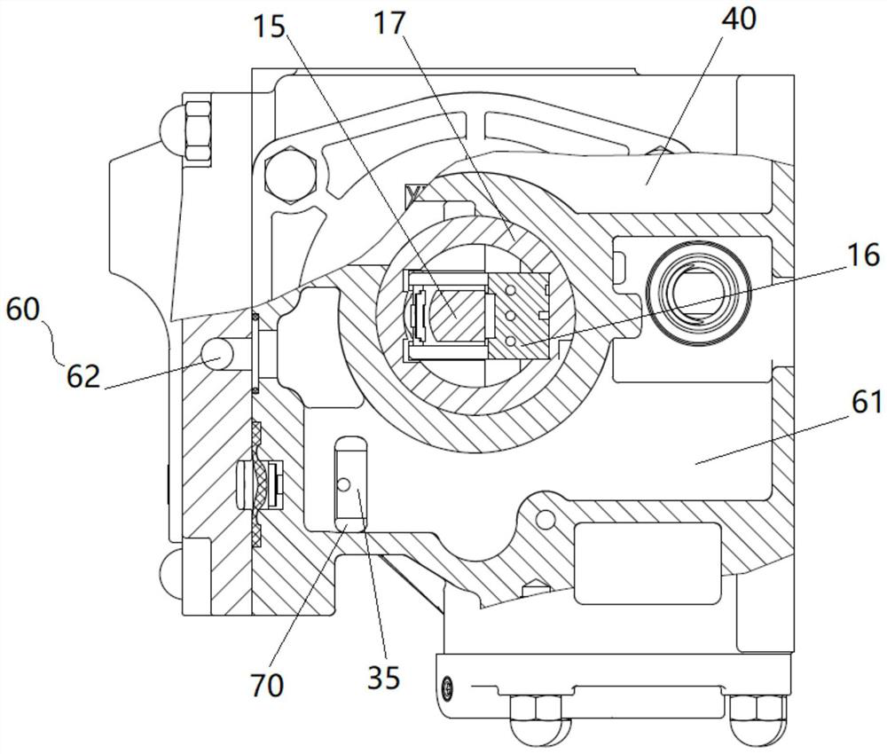
[0040] like Figure 1 to Figure 9As shown, an embodiment of the present invention provides an air control valve with an acceleration and mitigation function. The air control valve with an acceleration and mitigation function includes a main valve body 10, a relief valve body 20 and a relief valve core 30. The main valve body 10 has an interval The main valve upper chamber 11 and the main valve lower chamber 12 are provided, the main valve upper chamber 11 is communicated with the train pipe 100, the main valve lower chamber 12 is communicated with the auxiliary air cylinder 110, and the relief valve body 20 has drive chambers 21 arranged at intervals. and the inflatable chamber 22, the air inlet of the inflatable chamber 22 is communicated with the acceleration and relief air cylinder 120, the air outlet of the inflatable chamber 22 is communicated with the train pipe 100, the relief valve core 30 is movably arranged in the drive chamber 21, and the relief valve core 30 divides the drive cavity 21 into a train cavity 211 and an auxiliary air cavity 212, the train cavity 211 is communicated with the train pipe 100, the auxiliary air cavity 212 is communicated with the lower cavity 12 of the main valve, and the end of the relief valve core 30 is provided with a protruding cavity. The blocking member 31 of the inflatable chamber 22 has a communication position connecting the air outlet and the air inlet of the inflatable chamber 22 and a closed position separating the air outlet and the air inlet of the inflatable chamber 22 .
[0041] By applying the technical solution of the present invention, when the train is relieved, the locomotive fills the braking system of each vehicle of the train with pressurized air through the train pipe 100. Since the train pipe 100 is pressurized, and the air pressure in the train pipe 100 is greater than that of the auxiliary air cylinder 110 When the air pressure in the train cavity 211 is communicated with the train pipe 100, and the auxiliary air cavity 212 is communicated with the auxiliary air cylinder 110, the pressure in the train cavity 211 will be higher than the pressure in the auxiliary air cavity 212, and the sealing The blocking member 31 is in the communication position, so that the air inlet of the inflation chamber 22 is connected with the air outlet, and the air in the acceleration and relief air cylinder 120 enters the train tube 100 through the inflation chamber 22 to inflate the train tube 100, so that the train tube 100 is inflated. The gas pressure in the 100 rises faster, inflating the brake system faster, and the relief of the train is better.
[0042] In this embodiment, the blocking member 31 has a communication position that communicates with the air outlet and the air inlet of the inflatable cavity 22 and a closed position that blocks the air outlet and the air inlet of the inflatable cavity 22. It means that the blocking member 31 can The air inlet of the inflatable chamber 22 is opened, so that the air outlet of the inflatable chamber 22 is communicated with the air inlet, and the blocking member 31 is in the communication position at this time. In addition, the blocking member 31 can block the air outlet of the inflatable cavity 22, so that the air outlet of the inflatable cavity 22 is separated from the air inlet, and the blocking member 31 is in a closed position at this time.
[0043] It should be noted that the lower chamber 12 of the main valve communicates with the train pipe 100 , and the pressurized air in the auxiliary air cylinder 110 is charged through the train pipe 100 . However, a shrinkage block is provided between the train pipe 100 and the lower chamber 12 of the main valve, so that the inflation speed of the upper chamber 11 of the main valve is higher than that of the lower chamber 12 of the main valve.
[0044] When the train brakes, pressurized air is filled into the brake cylinder through the auxiliary air cylinder 110, so that the brake piston of the brake cylinder drives the brake shoe connected to the lever, so that friction between the brake shoe and the wheel passes braking force.
[0045] like Figure 1 to Figure 6 as well as Figure 8 As shown, the main valve body 10 and the relief valve body 20 are integrally formed, and the relief valve body 20 and the main valve body 10 together form the control valve body 40 . The control valve body 40 with the above structure has the advantages of compact structure and convenient miniaturization.
[0046] In this embodiment, the extension direction of the main valve body 10 and the relief valve body 20 are perpendicular to each other, which has the advantage of facilitating communication.
[0047] like figure 1 and figure 2 As shown, the control valve body 40 has a relief passage 50, the air inlet of the relief passage 50 is communicated with the acceleration relief air cylinder 120, the air outlet of the relief passage 50 is communicated with the air inlet of the inflation chamber 22, and the relief passage 50 is adopted, It has the advantage of being convenient to communicate with the air inlet of the acceleration relief air cylinder 120 and the inflation chamber 22, and is convenient for the miniaturization of the control valve body.
[0048] The relief passage 50 is provided with a check valve 51 , and the check valve 51 has a blocking position for blocking the air inlet of the acceleration relief air cylinder 120 and the inflatable cavity 22 and an air inlet for connecting the acceleration relief air cylinder 120 and the inflatable chamber 22 open position. With the check valve 51 , when the train pipe 100 is inflated to the braking system, the air in the train pipe 100 can be prevented from being directly charged into the acceleration relief air cylinder 120 through the relief passage 50 , thereby avoiding accidents on the train.
[0049] It should be noted that the check valve 51 has a blocking position for blocking the air intake of the acceleration and mitigation air cylinder 120 and the inflatable cavity 22 and an opening position for connecting the air intake of the acceleration and mitigation air cylinder 120 and the inflatable cavity 22, which means, The check valve 51 can block the relief passage 50 and block the air charging passage from the train pipe 100 to the acceleration relief air cylinder 120 . When the check valve 51 is in the blocking position, the disconnection between the air cylinder 120 and the air inlet of the charging chamber 22 is accelerated and relieved. When the check valve 51 is in the open position, the air intake passage between the air cylinder 120 and the charging chamber 22 is accelerated and relieved.
[0050] like figure 1 and Figure 8 As shown, the main valve body 10 includes a main valve body 13 and a main valve lower cover 14 covered on the main valve body 13, and the relief passage 50 includes a relief section 52, a relief section 53, a relief section 54, and a relief section 4. Section 55, the air inlet of the first section 52 of the relief is connected with the acceleration and relief air cylinder 120, the first section of relief 52 is arranged on the control valve body 40 and extends in the horizontal direction, and the second section of relief 53 is arranged in the control valve body 40 and extends in the vertical direction. , the third section of relief 54 is arranged on the lower cover 14 of the main valve and extends in the horizontal direction, the fourth section of relief 55 is arranged on the control valve body 40 and extends in the vertical direction, the outlet of the fourth section of relief 55 and the air inlet of the inflatable cavity 22 connected. The main valve body 10 with the above structure has the advantage of being easy to process and assemble.
[0051] In this embodiment, the check valve 51 is arranged in the second relief stage 53 , so that the space of the main valve body 10 can be fully utilized.
[0052] like figure 1 As shown, the check valve 51 includes a check valve core 511 and a first return spring 512, and the second relief section 53 includes a reducing diameter section 531 and an expanding diameter section 532 that communicate with each other. The section 532 corresponds to the air outlet of the diameter-reducing section 531 , and both ends of the first return spring 512 abut with the main valve lower cover 14 and the check valve core 511 respectively. The check valve with the above structure has the advantages of simple structure and easy installation. In addition, the use of the first return spring 512 can realize the automatic return of the check valve core.
[0053] In this embodiment, a vent pipe is also provided above the check valve 51, and the upper surface of the check valve core 511 is in contact with the lower surface of the vent pipe. The above structure has the advantage of being easy to process, so that the check valve core 511 can be enhanced. The contact area between the reverse valve core 511 and the vent pipe.
[0054] like figure 2 and image 3 As shown, the control valve body 40 has a train passage 60 , the air inlet of the train passage 60 is communicated with the train pipe 100 , and the air outlet of the train passage 60 is communicated with the train cavity 211 . The use of the train passage 60 has the advantage of facilitating the connection between the train pipe 100 and the air outlet of the inflatable cavity 22 , which is beneficial to the miniaturization of the control valve body 40 .
[0055] like figure 2 and image 3 As shown, the relief valve body 20 includes a relief valve body 23 and a relief valve cover 24 covered on the relief valve body 23. The train passage 60 includes a first train section 61 and a second train section 62 that communicate with each other. The air intake of the first train section 61 is connected to the The train pipes 100 communicate with each other, the first train section 61 is arranged on the control valve body 40 and extends in the horizontal direction, the second train section 62 is arranged on the relief valve cover 24 , and the air outlet of the second train section 62 communicates with the train cavity 211 . The relief valve body 20 with the above structure has the advantage of being easy to process and assemble.
[0056] It should be noted that the second section 62 of the train includes a vertical section and a horizontal section that are connected, which has the advantage of being easy to process.
[0057] like image 3 As shown, the control valve body 40 has a backfill channel 70 , the air inlet of the backfill channel 70 is communicated with the air outlet of the charging chamber 22 , and the air outlet of the backfill channel 70 is communicated with the train section 61 . The use of the backfill channel 70 has the advantage of being convenient to communicate the air outlet of the first section 61 of the train with the air outlet of the inflation chamber 22 , which is beneficial to the miniaturization of the control valve body 40 .
[0058] like Figure 5 As shown, the control valve body 40 has a secondary air passage 80 , the air inlet of the secondary air passage 80 is communicated with the lower chamber 12 of the main valve, and the air outlet of the secondary air passage 80 is communicated with the secondary air chamber 212 . The use of the backfilling channel 70 has the advantage of facilitating the communication between the lower chamber 12 of the main valve and the auxiliary air chamber 212 , and is beneficial to the miniaturization of the control valve body 40 .
[0059] like Figure 8 As shown, the main valve body 10 is provided with a piston rod 15, a slide valve 16 and a slide valve sleeve 17, the piston rod 15 is movably arranged in the main valve body 10, and the piston rod 15 divides the inner cavity of the main valve body 10 into The upper chamber 11 of the main valve and the lower chamber 12 of the main valve, the outer side wall of the spool valve sleeve 17 is in contact with the cavity wall of the lower chamber 12 of the main valve, and one side of the spool valve 16 is in contact with the inner side wall of the spool valve sleeve 17, The other side of the slide valve 16 is embedded in the piston rod 15 , the slide valve sleeve 17 is provided with a communication hole 171 , and the communication hole 171 communicates with the auxiliary air passage 80 . The piston rod 15 can drive the spool valve 16 to move, and then the spool valve 16 can be communicated with the corresponding passage of the spool valve sleeve 17, so that the braking system of the train can be in different states, and the train can be braked or relieved. Moreover, by disposing the communication hole 171 on the spool valve sleeve 17 , it has the advantage of facilitating the communication between the lower chamber 12 of the main valve and the auxiliary air chamber 212 .
[0060] In this embodiment, in the initial charging stage of the train, since the charging speed of the upper chamber 11 of the main valve is greater than the charging speed of the lower chamber 12 of the main valve, the piston rod 15 can be moved downward under the action of the driving pressure difference, and further The spool valve 16 and the spool valve sleeve 17 can be in a channel communicating with the train pipe 100 to inflate the acceleration relief air cylinder 120 , so that the train pipe 100 can be used to inflate the acceleration relief air cylinder 120 .
[0061] Specifically, when the train is in the inflation relief state, the pressure air in the acceleration relief air cylinder 120 may be charged into the train pipe 100 through the train section 61 by using the backfill channel 70 .
[0062] like figure 1 and figure 2 As shown, the relief valve core 30 includes a connected valve stem 32 and a valve cap 33, the blocking member 31 is a blocking valve core 311 disposed at the first end of the valve stem 32, and the valve cap 33 separates the drive cavity 21 into a train cavity 211 and auxiliary air cavity 212 . The relief valve core 30 with the above structure has the advantage of simple structure.
[0063] like figure 1 and figure 2 As shown, the relief valve core 30 further includes a locking nut 34 connected with the valve stem 32, the valve stem 32 has an annular protrusion, and the valve cap 33 is sandwiched between the locking nut 34 and the annular protrusion, using a locking nut 34 connects the valve cap 33 with the valve stem 32, which has the advantage of simple structure.
[0064] In this embodiment, the valve cap 33 includes a first annular plate 331 , a second annular plate 332 and an elastic sheet 333 . The outer ring of the elastic sheet 333 is connected to the relief valve body 20 , and the inner ring of the elastic sheet 333 is sandwiched between the first and second annular plates 333 . Between the annular plate 331 and the second annular plate 332, the elastic sheet 333 divides the drive cavity 21 into the train cavity 211 and the auxiliary air cavity 212. The first annular plate 331 is fitted with the locking nut 34, and the second annular plate 332 is The annular protrusions fit together, and the valve cap 33 with the above structure has the advantage of being easy to install.
[0065]Specifically, the relief valve body 20 further includes a valve sleeve 35, the valve sleeve 35 is arranged in the inner cavity of the relief valve body 20, and the valve sleeve 35 divides the inner cavity of the relief valve body 20 into a driving cavity 21 and an inflation cavity 22, and the valve stem 32 The first end of the valve can be movably passed through the valve sleeve 35, the valve sleeve 35 can provide a guiding function for the valve stem 32, and the valve sleeve 35 can be used to separate the relief valve body 20, which has the advantage of multi-purpose.
[0066] In this embodiment, the outer side wall of the valve sleeve 35 is abutted with the cavity wall of the inner cavity of the relief valve body 20 , so that the inner cavity of the relief valve body 20 is divided into the driving cavity 21 and the inflation cavity 22 .
[0067] The valve sleeve 35 has a valve port that communicates with the air inlet and the air outlet of the inflatable chamber 22, and the blocking valve core 311 is movably arranged at the valve port. With the above structure, the valve sleeve 35 can be connected to the valve sleeve 35 by the blocking valve core 311. For blocking, it has the advantage of simple structure.
[0068] It should be noted that the valve port is located in the middle of the valve sleeve 35, the valve sleeve 35 has a through-returning hole, one end of the reverse-filling hole is connected with the valve port, and the other end of the reverse-filling hole is connected with the reverse-filling channel 70, and then The pressurized air in the acceleration relief air cylinder 120 may be charged into the train pipe 100 through the reverse charging hole.
[0069] In this embodiment, the relief valve body 20 further includes a second return spring 25 and a support plate 26 . The support plate 26 is located on the side of the blocking valve core 311 away from the relief valve core 30 , and the outer edge of the support plate 26 is connected to the valve sleeve 35 . The inner side walls of the second return spring 25 are connected to each other, and the two ends of the second return spring 25 are respectively in contact with the blocking valve core 311 and the support plate 26. The support plate 26 is provided with ventilation holes, and the support plate 26 can be used to support the second return spring 25 , the use of the second reset spring 25 can realize the automatic reset of the blocking valve core, which has the advantages of simple structure and easy installation.
[0070] It should be noted that the terminology used herein is for the purpose of describing specific embodiments only, and is not intended to limit the exemplary embodiments according to the present application. As used herein, unless the context clearly dictates otherwise, the singular is intended to include the plural as well, furthermore, it is to be understood that when the terms "comprising" and/or "including" are used in this specification, it indicates that There are features, steps, operations, devices, components and/or combinations thereof.
[0071] The relative arrangement of the components and steps, the numerical expressions and numerical values ​​set forth in these embodiments do not limit the scope of the invention unless specifically stated otherwise. Meanwhile, it should be understood that, for the convenience of description, the dimensions of the various parts shown in the drawings are not drawn according to the actual proportional relationship. Techniques, methods, and apparatus known to those of ordinary skill in the relevant art may not be discussed in detail, but where appropriate, such techniques, methods, and apparatus should be considered part of the specification. In all examples shown and discussed herein, any specific value should be construed as illustrative only and not as limiting. Accordingly, other examples of exemplary embodiments may have different values. It should be noted that like numerals and letters refer to like items in the following figures, so once an item is defined in one figure, it does not require further discussion in subsequent figures.
[0072] In the description of the present invention, it should be understood that the orientations indicated by orientation words such as "front, rear, top, bottom, left, right", "horizontal, vertical, vertical, horizontal" and "top, bottom" etc. Or the positional relationship is usually based on the orientation or positional relationship shown in the drawings, which is only for the convenience of describing the present invention and simplifying the description, and these orientations do not indicate or imply the indicated device or element unless otherwise stated. It must have a specific orientation or be constructed and operated in a specific orientation, so it cannot be construed as a limitation on the protection scope of the present invention; the orientation words "inside and outside" refer to the inside and outside relative to the outline of each component itself.
[0073] For ease of description, spatially relative terms, such as "on", "over", "on the surface", "above", etc., may be used herein to describe what is shown in the figures. The spatial positional relationship of one device or feature shown to other devices or features. It should be understood that spatially relative terms are intended to encompass different orientations of the device in use or operation in addition to the orientation depicted in the figures. For example, if the device in the figures is turned over, elements described as "above" or "over" other devices or features would then be oriented "below" or "over" the other devices or features under other devices or constructions". Thus, the exemplary term "above" can encompass both an orientation of "above" and "below." The device may also be otherwise oriented (rotated 90 degrees or at other orientations) and the spatially relative descriptions used herein interpreted accordingly.
[0074] In addition, it should be noted that the use of words such as "first" and "second" to define components is only for the convenience of distinguishing corresponding components. Unless otherwise stated, the above words have no special meaning and therefore cannot be understood to limit the scope of protection of the present invention.
[0075] The above descriptions are only preferred embodiments of the present invention, and are not intended to limit the present invention. For those skilled in the art, the present invention may have various modifications and changes. Any modification, equivalent replacement, improvement, etc. made within the spirit and principle of the present invention shall be included within the protection scope of the present invention.

PUM

no PUM

Description & Claims & Application Information

We can also present the details of the Description, Claims and Application information to help users get a comprehensive understanding of the technical details of the patent, such as background art, summary of invention, brief description of drawings, description of embodiments, and other original content. On the other hand, users can also determine the specific scope of protection of the technology through the list of claims; as well as understand the changes in the life cycle of the technology with the presentation of the patent timeline. Login to view more.

Similar technology patents

Method for correcting falling direction and lowering falling speed of human body

InactiveCN104554731AEasy to operatequick inflation
Owner:DONGGUAN ALBIYA ENERGY SCI & TECH

Method for relieving phytotoxicity effect of atrazine on soybeans through inoculation of rhizobium

PendingCN112931123AGood reliefnodulation inhibition
Owner:NORTHEAST AGRICULTURAL UNIVERSITY

Classification and recommendation of technical efficacy words

  • quick inflation

Method for correcting falling direction and lowering falling speed of human body

InactiveCN104554731AEasy to operatequick inflation
Owner:DONGGUAN ALBIYA ENERGY SCI & TECH
Why Eureka
Try Eureka