Automatic raw material elevator for non-ferrous metal calendering processing

A technology of rolling processing and non-ferrous metals, which is applied in the direction of conveyors, mechanical conveyors, conveyor objects, etc., can solve the problems of workers falling from heights and large safety hazards, so as to improve output efficiency and reduce the probability of spilling , The effect of reducing the probability of safety accidents

Inactive Publication Date: 2022-07-29
徐州锋儒智能科技有限公司
View PDF0 Cites 0 Cited by
  • Summary
  • Abstract
  • Description
  • Claims
  • Application Information

AI Technical Summary

Problems solved by technology

[0003] After the raw materials are conveyed by the automatic hoist, it is necessary to manually drag the raw materials. The raw materials conveyed by the hoist here will rise to a certain height, so workers need to be as close to the raw materials as possible, so that it is convenient to take out the raw materials, which poses a great safety hazard and is easy to A worker falls from a height

Method used


Image

  • Automatic raw material elevator for non-ferrous metal calendering processing
  • Automatic raw material elevator for non-ferrous metal calendering processing
  • Automatic raw material elevator for non-ferrous metal calendering processing

Examples


Embodiment 1

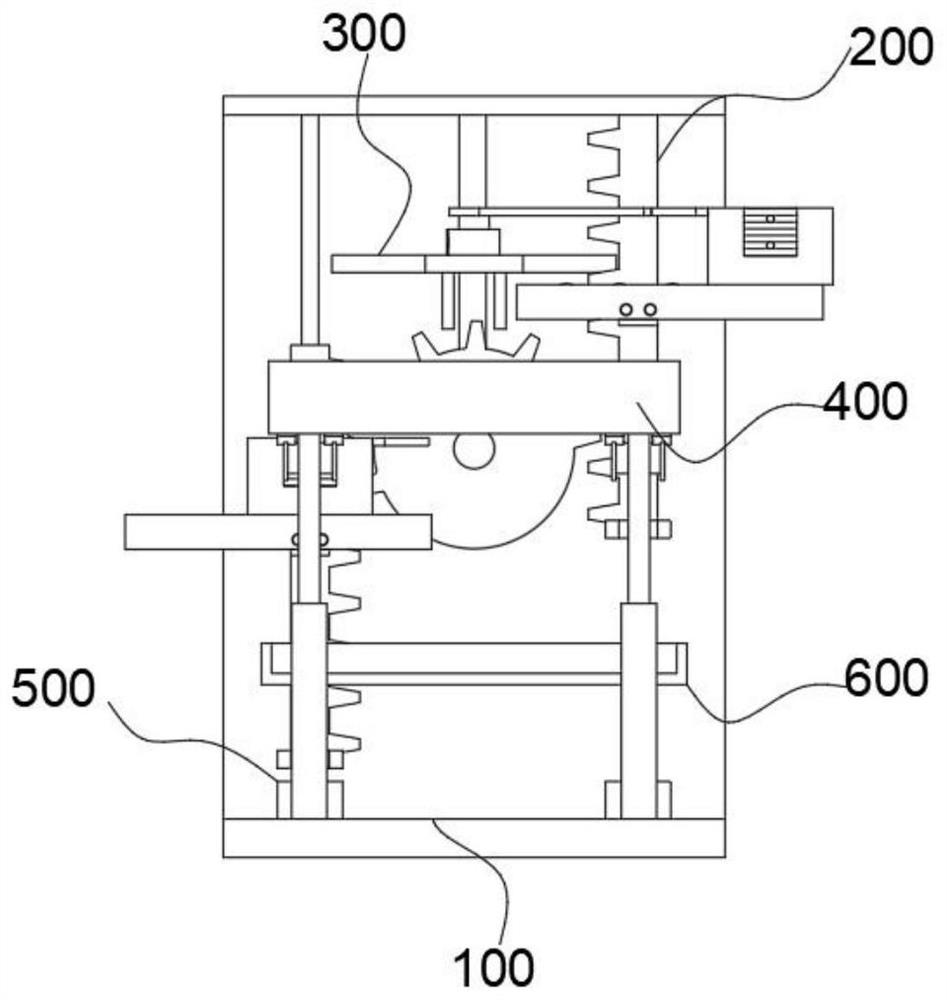
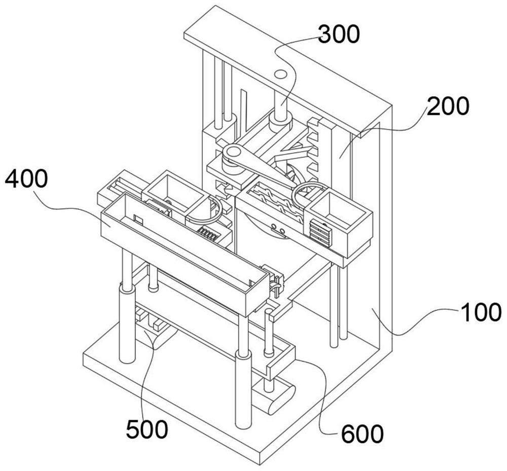
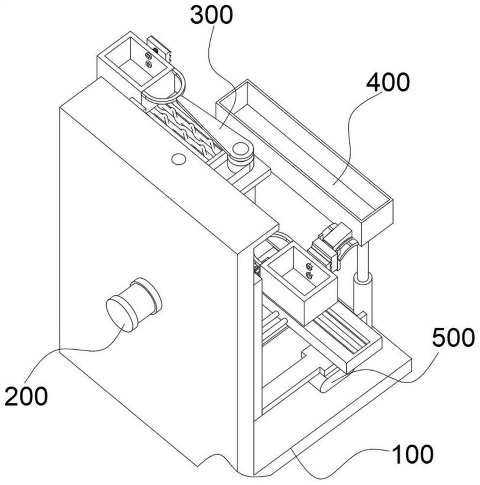
[0045] combine Figure 1-8 As shown, the present invention provides an automatic hoist for raw materials for non-ferrous metal calendering processing, including a frame 100, and the frame 100 is provided with a feeding module 200, a pushing module 300, a discharging module 400 and a control module 500, The feeding module 200 includes a motor 210 installed on the rear side of the rack 100 , an incomplete gear 220 located on the front side of the rack 100 and connected to the output shaft of the motor 210 , and the incomplete gear 220 Two toothed plates 230 that are symmetrical and meshed with the incomplete gears 220 , a plurality of guide rods 240 that slide through the two toothed plates 230 and are connected to the frame 100 , are installed in front of the toothed plates 230 The supporting plate 250 on the side, the material frame 260 slidably installed on the top of the supporting plate 250 , and the two round rods 270 embedded in the top of the supporting plate 250 and sli...

Embodiment 2

[0054] combine Image 6 As shown, on the basis of Embodiment 1, there is a gap between the rear side of the incomplete gear 220 and the front side of the frame 100, the first bevel gear 330 and the second bevel gear 340 are located inside the gap, and the gap Provide installation space for the first bevel gear 330 and the second bevel gear 340 to ensure that the first shaft 320 can rotate smoothly, thereby indirectly rotating the second shaft 350 and the push rod 380 to ensure that the material frame 260 can be moved to a safe position.

Embodiment 3

[0056] combine Figure 1-3 As shown, in the above-mentioned embodiment, the top of the frame 100 is provided with a material receiving box 600, the material receiving box 600 is sleeved on the outside of the two hollow cylinders 520, and the material receiving box 600 is used for receiving self-discharging materials The raw materials dropped on the channel 430 can avoid waste of raw materials.

[0057] The working principle and use process of the present invention: after filling the raw material box 420 with raw materials, the device is put into practical use, firstly, the motor 210 connected with the incomplete gear 220 and the second bevel gear 340 is started, and then the incomplete gear 220 drives the The material frame 260 on the right side with the raw material is raised, and then the empty material frame 260 on the left side is lowered. When the left side material frame 260 is lowered, the second clamping plate 470 on the front side is connected to the first clamping pl...


PUM


Abstract

The invention discloses an automatic raw material elevator for non-ferrous metal calendaring processing, which comprises a rack, and a feeding module, a pushing module, a discharging module and a control module are arranged on the rack; the feeding module comprises a motor installed on the rear side of the rack, an incomplete gear located on the front side of the rack and connected with an output shaft of the motor, two toothed plates symmetrical about the incomplete gear and meshed with the incomplete gear, and a plurality of guide rods penetrating through the two toothed plates in a sliding mode and connected with the rack. And the supporting plate is mounted on the front side of the toothed plate. A motor drives a second bevel gear to rotate, the second bevel gear drives a first rotating shaft connected with the first bevel gear to rotate, then a belt pulley is matched with a belt, the second rotating shaft drives a push rod to rotate, and the push rod extrudes a material frame connected with a C-shaped plate outwards, so that the material frame is close to a floor as much as possible, and workers can conveniently and safely take out raw materials; and the probability of safety accidents is reduced.

Description

technical field [0001] The invention relates to the technical field of non-ferrous metal calendering processing, in particular to an automatic raw material elevator for non-ferrous metal calendering processing. Background technique [0002] The process of making semi-finished products such as films through the nip between two relatively rotating and horizontally arranged rollers is called calendering. The calendering mentioned here refers to the processing of non-ferrous metals. [0003] After the raw material is conveyed by the automatic elevator, it needs to be manually dragged. The raw material conveyed by the elevator here will rise to a certain height. Therefore, workers need to be as close to the raw material as possible, so that the raw material can be easily taken out. Workers have fallen from heights. SUMMARY OF THE INVENTION [0004] The present invention aims to solve one of the technical problems existing in the prior art or related technologies. [0005] Fo...

Claims


Application Information

Patent Timeline
Patent Type & Authority Applications(China)
IPC IPC(8): B65G35/00B65G47/82B65G47/34
CPCB65G35/00B65G47/82B65G47/34
Inventor 赵凤丹
Owner 徐州锋儒智能科技有限公司
Why Eureka
Try Eureka