
Liftable tower crane and lifting regulation and control method thereof

A tower crane and lift-type technology, applied in cranes and other directions, can solve the problems of convenience and inconvenience of increasing the working difficulty of tower cranes, and achieve the effect of increasing working difficulty and improving stability.

Pending Publication Date: 2022-07-29
射阳县广厦机械租赁有限公司
View PDF0 Cites 1 Cited by
  • Summary
  • Abstract
  • Description
  • Claims
  • Application Information

AI Technical Summary

Problems solved by technology

[0003] When the tower cranes in the prior art are in use, the tower body is installed layer by layer. When it is necessary to adjust the overall height of the tower crane, it can only be realized by installing the tower body, which greatly increases It is extremely inconvenient to understand the difficulty of working and the convenience of using the tower crane

Method used


Image

  • Liftable tower crane and lifting regulation and control method thereof
  • Liftable tower crane and lifting regulation and control method thereof
  • Liftable tower crane and lifting regulation and control method thereof

Examples


Embodiment 1

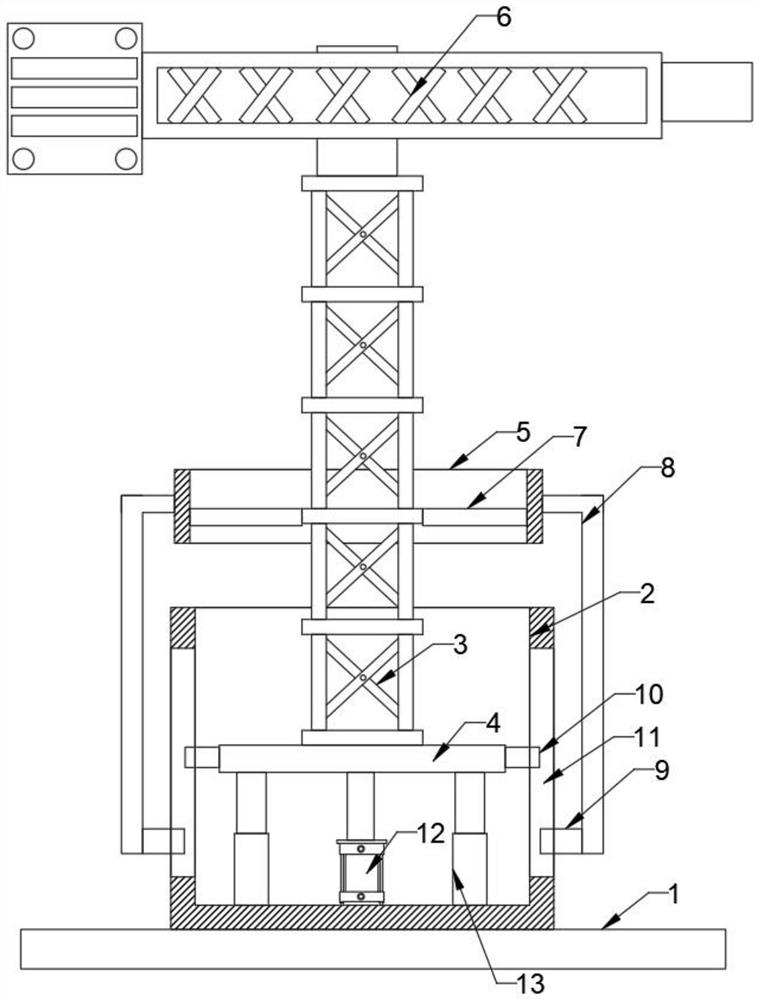
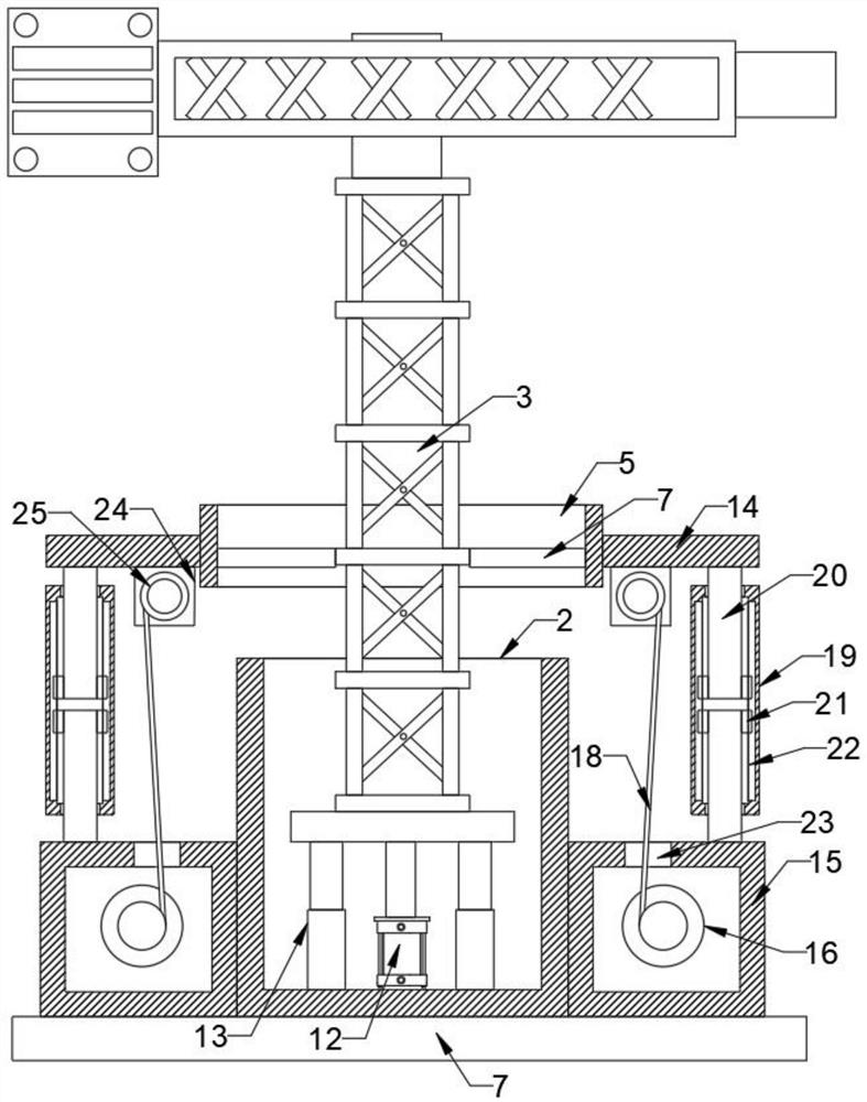
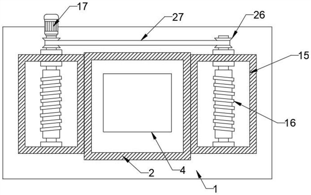
[0025] refer to Figure 1-4 , including the base 1, the bottom of the base 1 is fixedly connected with a bearing frame 2, and the inner side of the bearing frame 2 is slidably connected with a bearing plate 4, the top of the bearing plate 4 is installed with a tower body 3, and the top of the tower body 3 is installed with a lifting Arm 6, the inner bottom of the bearing frame 2 is fixedly connected with a large hydraulic cylinder 12 by bolts, and the output end of the large hydraulic cylinder 12 is fixedly connected with the bottom of the bearing plate 4, and the middle of the tower body 3 is sleeved with a top frame 5, And the inner wall of the top frame 5 is fixedly connected with the tower body 3 through the connecting plate 7, both sides of the bearing frame 2 are fixedly connected with the bottom frame 15, and one side of the two bottom frames 15 is fixedly connected with a bolt. The driving motor 17, the inner sides of the two bottom frames 15 are rotatably connected wi...

Embodiment 2

[0028] refer to Figure 1-4 , between the two side plates 14 and the tops of the two bottom frames 15 are respectively provided with a bearing tube 19, and the inner upper part and the inner lower part of the bearing tube 19 are slidably connected with inner rods 20, and the two inner rods 20 are away from each other. One end of the two inner rods 20 is fixedly connected to the bottom of the side plate 14 and the top of the bottom frame 15 respectively, and one end of the four inner rods 20 is connected to the two carrying pipes 19 respectively. The poles are all sliding connections, the two sides of the four inner rods 20 are fixedly connected with sliding blocks 21, and the sliding blocks 21 are slidably connected with the inner wall of the bearing tube 19 through the sliding groove 22;

[0029] The inner rod 20 is used to slide in the carrier tube 19 , thereby further improving the stability of the tower body 3 as a whole during lifting and lowering.

Embodiment 3

[0031] refer to Figure 1-4 , the lifting control method includes the following steps:

[0032] S1: Start the large hydraulic cylinder 12 to drive the bearing plate 4 to move up and down in the bearing frame 2, so that the tower body 3 can be adjusted up and down;

[0033] S2: At the same time, when the tower body 3 moves up and down, the driving motor is started to drive the winding rod 16 to rotate, so that the tower body 3 can be moved up and down while maintaining the stability of the tower body 3 through the steel cable 18;

[0034] S3: When the tower body 3 moves up and down, the two inner rods 20 inside the carrying tube 19 will expand and contract, and the stability of the tower body 3 can be further improved.


PUM


Abstract

The invention relates to the technical field of cranes, in particular to a liftable tower crane and a lifting regulation and control method thereof, and solves the technical problems that a tower body is mounted layer by layer when the tower crane in the prior art is used, the overall height of the tower crane can only be regulated by mounting the tower body, and the tower crane is inconvenient to use. And therefore, the working difficulty and the use convenience of the tower crane are greatly improved. The liftable tower crane comprises a base, the bottom of the base is fixedly connected with a bearing frame, the inner side of the bearing frame is slidably connected with a bearing plate, the top of the bearing plate is provided with a tower body, and the top end of the tower body is provided with a cargo boom. According to the mode provided by the invention, the lifting adjustment of the tower body can be realized through the bearing frame and the components thereof, and the stability of the tower body can be greatly improved by utilizing the bottom frame, the components and the bearing pipe.

Description

technical field [0001] The invention relates to the technical field of cranes, in particular to a liftable tower crane and a lift control method thereof. Background technique [0002] A tower crane is a slewing crane whose boom is mounted on the top of a towering tower. It has a large working range and is mainly used for vertical transportation of materials and component installation in multi-storey and high-rise building construction. It consists of three parts: metal structure, working mechanism and electrical system. Metal structures include towers, booms, bases, attachment rods, etc. The working mechanism has four parts: lifting, luffing, turning and walking. The electrical system includes motors, controllers, power distribution boxes, connecting lines, signals and lighting devices. [0003] When the tower crane in the prior art is in use, the tower body is installed layer by layer. When the overall height of the tower crane needs to be adjusted, it can only be achie...

Claims


Application Information

Patent Timeline
Patent Type & Authority Applications(China)
IPC IPC(8): B66C23/30B66C23/32
CPCB66C23/30B66C23/32
Inventor 孙才业
Owner 射阳县广厦机械租赁有限公司
Learn More