Novel lifting equipment for inspecting water-cooled wall tube in boiler

A technology for water-cooled wall pipes and lifting equipment, which is applied in the direction of lifting equipment safety devices, lifting devices, etc., can solve the problems of affecting the heating safety of the unit, low work efficiency, safety accidents, etc., to avoid safety accidents, easy to use, and easy to operate. simple effect

Pending Publication Date: 2022-07-29
呼伦贝尔安泰热电有限责任公司汇流河发电厂
0 Cites 0 Cited by

AI-Extracted Technical Summary

Problems solved by technology

At present, in the field of lifting, fully enclosed guardrails and grid guardrails are mainly used. The quality of the fully enclosed guardrails is relatively heavy, which can prevent things on the lifting platform from falling from the lifting platform and cause accident...

Method used

Further, the rotating assembly 200 connects the earrings provided on the top of the lifting plate 103 by a stay cord, and rotating the rotating member 202 can make the turning wheel 201 carry out retracting and unwinding of the stay cord, thereby realizing that the rising and falling of the lifting plate 103 is more convenient .
Preferably, grid guardrail 102 is compared with the guardrail of fully enclosed all around, and quality is more portable, utilizes lift plate 103, can solve the problem that maintenance tool has fallen from lift platform 101 periphery; The addition of lift plate 103, b...

Abstract

The invention discloses a novel lifting device for inspection of a water wall tube in a boiler, the novel lifting device comprises a lifting assembly and a rotating assembly, the lifting assembly comprises a lifting table, a grid guardrail and a lifting plate, the grid guardrail is fixed at the top of the lifting table, and the lifting plate is arranged in the grid guardrail; the rotating assembly, the rotating wheel and the rotating piece are fixed to the top end of the grid guardrail, and the rotating piece penetrates through the rotating wheel. The grid guardrail is combined with the lifting plate, so that the problem of heavy weight of the guardrail with totally closed periphery can be solved, maintenance tools on the lifting platform cannot fall from the periphery, and safety accidents are avoided; the lifting of the lifting plate can be better controlled through the rotating assembly, operation is easy, and use is easy.

Application Domain

Safety devices for lifting equipments

Technology Topic

Industrial engineeringLifting equipment

Image

  • Novel lifting equipment for inspecting water-cooled wall tube in boiler
  • Novel lifting equipment for inspecting water-cooled wall tube in boiler
  • Novel lifting equipment for inspecting water-cooled wall tube in boiler

Examples

  • Experimental program(3)

Example Embodiment

[0030] Example 1
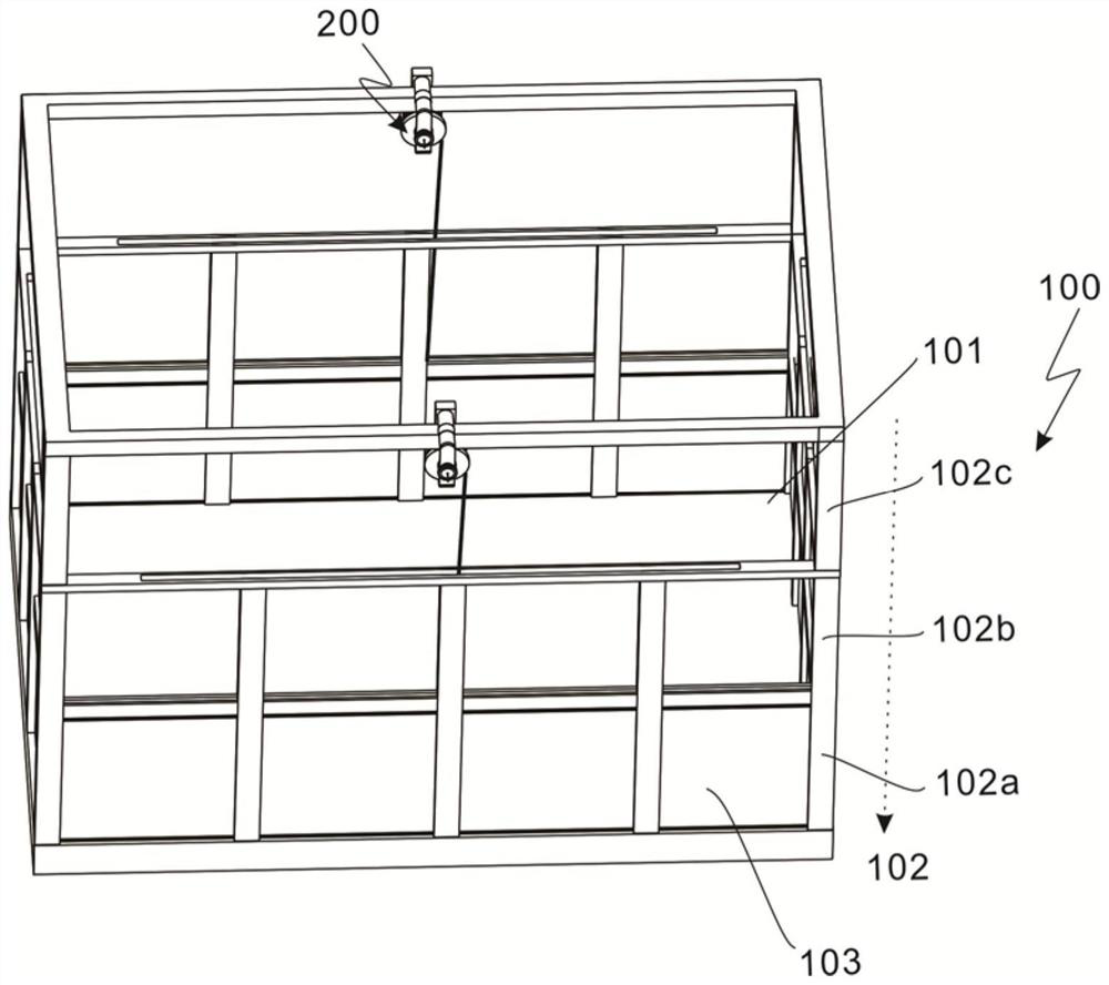
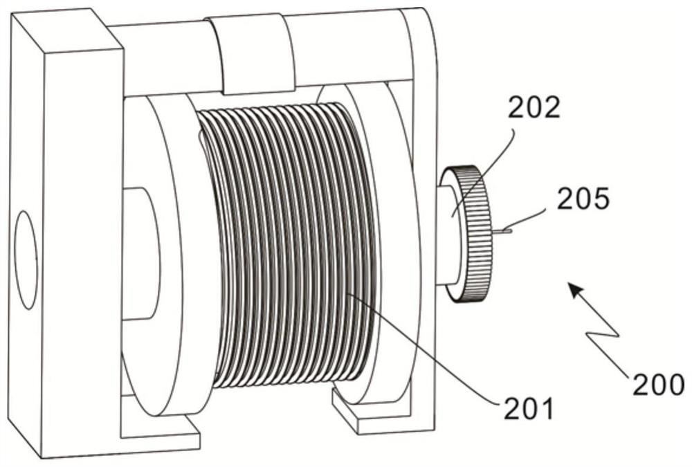
[0031] refer to Figure 1 to Figure 3 , which is the first embodiment of the present invention, which provides a new type of lifting equipment for inspecting water-cooled wall tubes inside a boiler, including a lifting assembly 100 and a rotating assembly 200. The lifting assembly 100 includes a lifting platform 101, a grid guardrail 102 and a lifting device The plate 103, the grid guardrail 102 is fixed on the top of the lifting platform 101, the lifting plate 103 is arranged in the grid guardrail 102; the rotating assembly 200, the rotating wheel 201 and the rotating member 202, the rotating member 202 is fixed on the top of the grid guardrail 102, the rotating member 202 passes through the rotating wheel 201.
[0032] Preferably, the grid guardrail 102 is lighter in quality than the guardrails that are fully enclosed around it. The use of the lift plate 103 can solve the problem that the maintenance tool has fallen from the periphery of the lift table 101; the addition of the lift plate 103 can prevent maintenance. The tool falling from the lift table 101 can also make the cleaning of the lift table 101 more convenient for the staff.
[0033] Further, the rotating assembly 200 is connected to the earrings provided on the top of the lifting plate 103 through a pulling rope, and rotating the rotating member 202 enables the rotating wheel 201 to retract and pay off the pulling rope, so that the lifting and lowering of the lifting plate 103 is more convenient.
[0034] By combining the grid guardrail and the lifting plate, the present invention can not only solve the problem of heavy quality of the guardrail that is fully enclosed around it, but also realize that the maintenance tools on the lifting platform 101 cannot fall from the periphery, so as to avoid safety accidents; The assembly 200 can better control the lifting and lowering of the lifting plate 103, and is simple to operate and easy to use.

Example Embodiment

[0035] Example 2
[0036] refer to Figure 1 to Figure 6 , is the second embodiment of the present invention, which is different from the previous embodiment in that: the grid guardrail 102 includes a first column 102a, a second column 102b and a third column 102c, and the first column 102a is fixed on the lifting platform At the top of 101, the first column 102a and the third column 102c are connected by the second column 102b.
[0037] The lift plate 103 reciprocates between the first column 102a and the second column 102b.
[0038] Preferably, the rotating assembly 200 is arranged on the top of the first column 102c, and the rotating member 202 can be rotated, so that the rotating wheel 201 can retract and pay off the pull rope, and drive the lifting plate to rise or fall, and the lifting plate 103 is pulled by the pull rope. Back and forth between the first column 102a and the second column 102b.
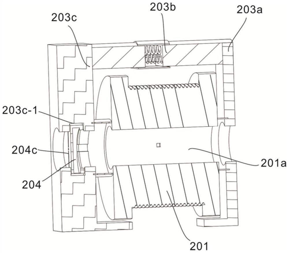
[0039] A connecting member 203 is provided on the outside of the rotating wheel 201. The connecting member 203 includes a connecting rod 203a, a first support plate 203b and a second support plate 203c. The connecting rod 203a is fixed on the top of the third column 102c. The two supporting plates 203c are connected to two ends of the connecting rod 203a.
[0040] Further, the rotating wheel 201 is connected with the third column 102c through the connecting piece 203 .
[0041] An annular groove 203c-1 is disposed in the second support plate 203c, and the rotating disk 204 is disposed in the annular groove 203c-1.
[0042] Further, the rotating plate 204 is arranged in the annular groove 203c-1. When the sliding block 204d is moved into the groove 204e, the positions of the rotating plate 204 and the second support plate 203c are locked, and the rotating plate 204 cannot be rotated. When the rotating member 202 is rotated, the rotating member 202 drives the rotating wheel 201 to rotate, the rotating wheel 201 starts to take up the wire, and the lifting plate 103 gradually moves from the first column 102a to the second column 102b.
[0043]One side of the rotating wheel 201 is provided with a through hole 201a, the rotating member 202 passes through the through hole 201a, a rectangular block 202a is set on the side of the rotating member 202 close to the second support plate 203c, and the side of the rectangular block 202a away from the second support plate 203c is set with a rectangular block 202a. The movable plate 202b, the movable plate 202b is connected with the rectangular block 202a through a loose leaf.
[0044] A vertical groove 204a is formed on one side of the rotating disk 204, and a rotating groove 204b is also provided inside the rotating disk 204. The vertical groove 204a is communicated with the rotating groove 204b.
[0045] Further, the rotating member 202 passes through the through hole 201a, and the rectangular block 202 disposed at one end of the rotating member 202 gradually enters the vertical groove 204a and extends toward the rotating groove 204b. When the rectangular block 202 moves to the rotating groove 204b, the rotating member 202 is rotated. , the rotating member 202 drives the rotating wheel 201 to rotate. It should be noted that when the rectangular block 202 is in the rotating groove 204b, the movable plate 202b connected to the rectangular block 202 through the loose leaf can only rotate in one direction, and the rotating member 202 can be rotated toward When rotating in one direction, the rectangular block 202 rotates in the rotating direction in the rotating groove 204b, the rectangular block 202 drives the rotating wheel 201 to rotate, the rotating wheel 201 starts to roll the rope, and the lifting plate 103 moves upward; when the rotating part is rotated in the opposite direction At 202, the movable plate 202b collides with the side wall of the vertical slot 204b and cannot rotate.

Example Embodiment

[0046] Example 3
[0047] refer to Figure 1 to Figure 9 , is the third embodiment of the present invention, which is different from the previous two embodiments in that the telescopic member 205 passes through the rotating member 202 and the rotating disk 204 .
[0048] Preferably, the telescopic member 205 passes through the rotating member 202 and the rotating disk 204 first, and locks and unlocks the rotating disk 204 .
[0049] The telescopic member 205 includes a moving rod 205a, a connecting sleeve 205b and a push rod 205c. The moving rod 205a passes through the rotating member 202 and the rotating disk 204. The connecting sleeve 205b is fixedly arranged on the other side of the rotating disk 204, and the sliding groove 204c is opened at the The other side of the rotating disk 204, one side of the sliding block 204d is arranged in the sliding groove 204c, and one end of the push rod 205c is rotatably connected with the moving rod 205a.
[0050] Further, the connecting sleeve 205b is fixedly arranged on the other side of the rotating disk 204, a plurality of bumps are arranged on both sides of the moving rod 205a, and the connecting sleeve 205b is provided with a chute and a ring groove, and the bumps enter through the chute. ring groove, so that the moving rod 205a no longer moves.
[0051] One end of the push rod 205c is connected to the sliding block 204d.
[0052] Further, one end of the push rod 205c is hinged with the sliding block 204d, and pushes the moving rod 205a in a direction away from the connecting sleeve 205b, the angle between the push rod 205c and the moving rod 205a becomes smaller, and the push rod 205c pulls and slides. The block 204d moves toward the direction of the moving rod 205a, the sliding block 204d leaves the groove 204e, and the lock between the rotating disk 204 and the second support plate 203c is released. When the lock between the rotating plate 204 and the second supporting plate 203c is released, the rotating member 202 is rotated in the direction, so that the rotating wheel 201 releases the pull rope, and the lifting plate 103 moves downward.
[0053] Further, when it is necessary to inspect the water-cooled wall tubes inside the boiler, first move the lifting table 101 to the required inspection position, and move the lifting plate 103 to the first column 102a to prevent the maintenance tools on the lifting table 101 from passing around. Falling will cause a safety accident; after the inspection, the lifting platform 101 needs to be hygienically maintained, and the rotating assembly 200 can be used to move the lifting plate 103 to the second column 102b. Pull the moving rod 205a toward the direction of the connecting sleeve 205b, the angle between the push rod 205c and the moving rod 205a becomes larger, the push rod 205c pulls the sliding block 204d to move away from the moving rod 205a, and the sliding block 204d enters the groove 204e, between the rotating plate 204 and the second support plate 203c is locked, the rotating plate 204 cannot be rotated, a vertical slot 204a is opened on one side of the rotating plate 204, and a rotating slot 204b is also arranged inside the rotating plate 204. The grooves 204b are connected, the rotating member 202 passes through the through hole 201a, and the rectangular block 202 disposed at one end of the rotating member 202 gradually enters the vertical groove 204a and extends toward the rotating groove 204b. When the rectangular block 202 is in the rotating groove 204b, it passes through the loose-leaf The movable plate 202b connected with the rectangular block 202 can only rotate in one direction. When the rotating member 202 is rotated in one direction, the rectangular block 202 rotates in the rotating direction in the rotating groove 204b, and the rectangular block 202 drives the rotating wheel 201 to rotate. , the rotating wheel 201 starts to roll the rope, the lifting plate 103 gradually moves from the first column 102a to the second column 102b, when the lifting plate 103 rises to the desired position, stop rotating the rotating member 202, at this time the movable plate 202b will move towards the second column 102b. The opposite direction of the rotation direction is slightly offset. When the movable plate 202b collides with the side wall of the vertical slot 204b, the movable plate 202b cannot drive the rotating wheel 201 to rotate.
[0054] Push the moving rod 205a away from the connecting sleeve 205b, the angle between the push rod 205c and the moving rod 205a becomes smaller, the push rod 205c pulls the sliding block 204d to move in the direction of the moving rod 205a, and the sliding block 204d leaves the groove 204e, the lock between the rotating plate 204 and the second supporting plate 203c is released; when the locking between the rotating plate 204 and the second supporting plate 203c is released, the rotating member 202 is rotated in the direction, so that the rotating wheel 201 will be pulled. The rope is released and the lift plate 103 moves downward.

PUM

no PUM

Description & Claims & Application Information

We can also present the details of the Description, Claims and Application information to help users get a comprehensive understanding of the technical details of the patent, such as background art, summary of invention, brief description of drawings, description of embodiments, and other original content. On the other hand, users can also determine the specific scope of protection of the technology through the list of claims; as well as understand the changes in the life cycle of the technology with the presentation of the patent timeline. Login to view more.

Similar technology patents

Dustproof anti-drop plug connector

InactiveCN108808352Aprevent electric sparksavoid safety accidents
Owner:ZHEJIANG XIAYUAN INFORMATION TECH CO LTD

Secure shower

Owner:中山市合硕高品电器有限公司

Classification and recommendation of technical efficacy words

  • avoid safety accidents
  • easy to operate

Child safety door fence

Owner:浙江鑫博婴童用品有限公司

Hinge device for kraut refrigerator

Owner:TAIZHOU LG ELECTRONICS REFRIGERATOR CO LTD

Guiding lighting system

InactiveCN102378434AAvoid safety accidentsEnsure long-distance vision
Owner:IDSYS

Lancet device

InactiveUS7303573B2inexpensively mass-producedeasy to operate
Owner:ABBOTT DIABETES CARE INC

Rapid and non-invasive optical detection of internal bleeding

InactiveUS20050065436A1easy to operaterapid and accurate result
Owner:HO WINSTON ZONH +2
Why Eureka
Try Eureka