[0024] In order to make it easy to understand the technical means, creative features, achieved goals and effects of the present invention, the present invention will be further described below with reference to the specific embodiments.
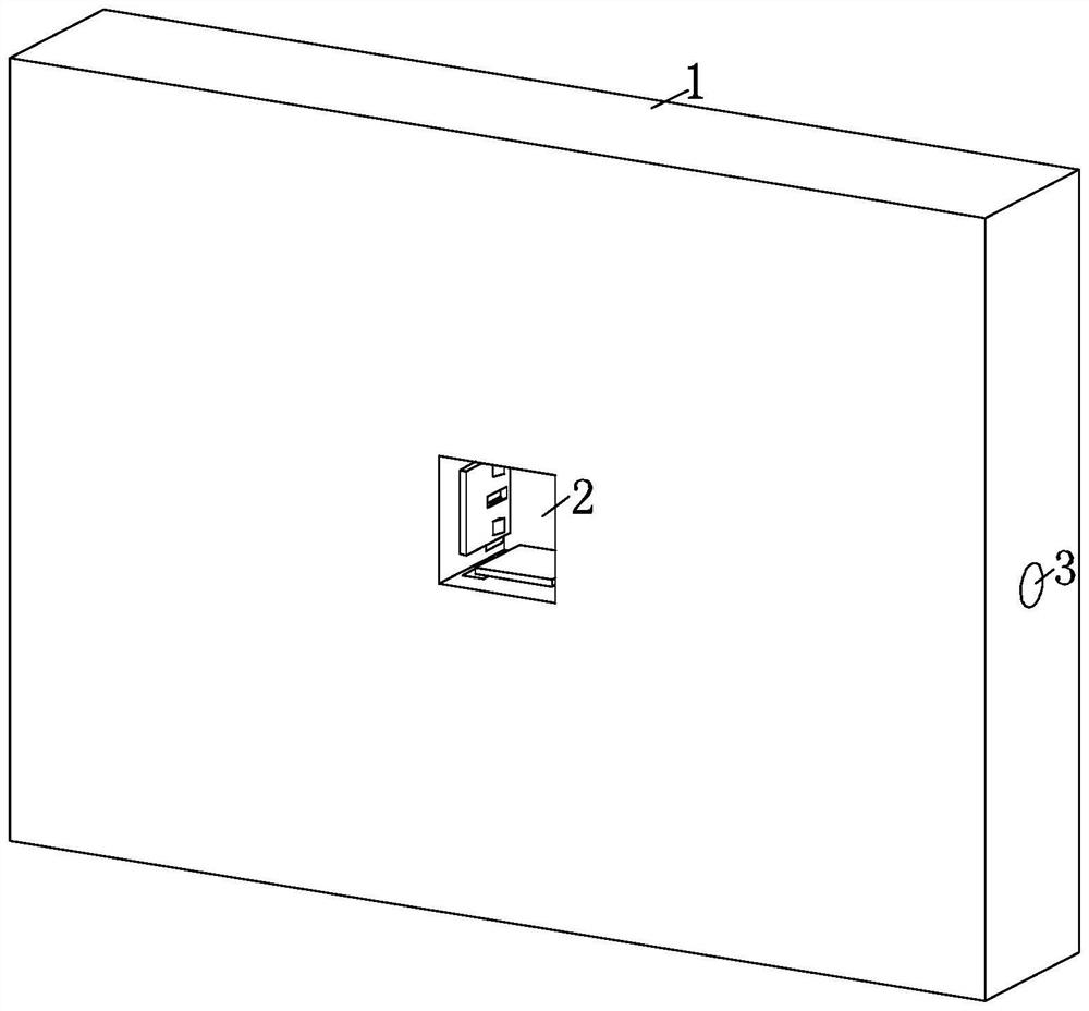
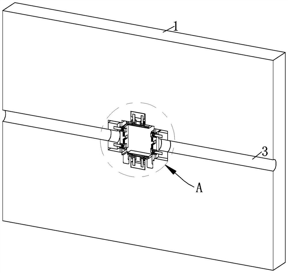
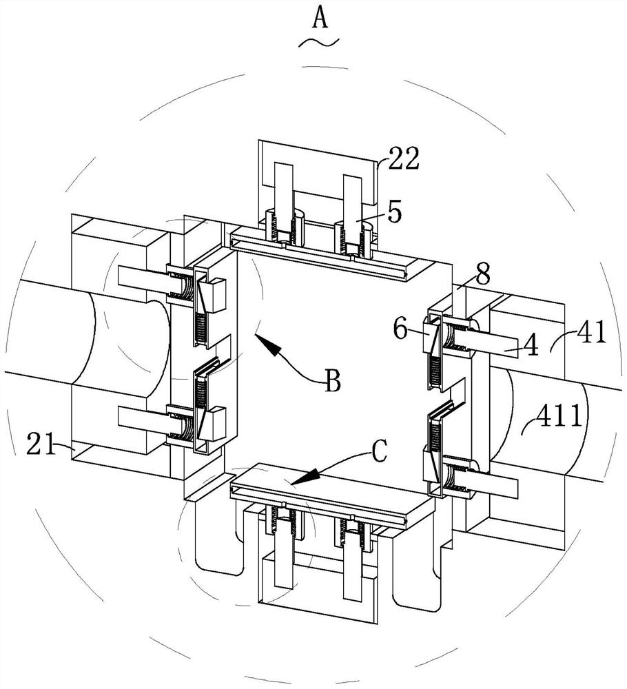
[0025] like Figure 1-Figure 6 As shown in the figure, a foamed concrete thermal insulation board according to the present invention includes a board body 1, a first groove body 2 for installing a switch cassette is arranged in the middle of one side of the board body 1, and the inner part of the board body 1 is along the A first through hole 3 for the line to pass through is provided in the horizontal direction, and the first through hole 3 passes through the two side walls of the first groove body 2 in the vertical direction. The vertical direction of the first groove body 2 and A lateral clamping mechanism 4 and a longitudinal clamping mechanism 5 for clamping the switch cassette are symmetrically installed on the side walls in the horizontal direction, and a limiting mechanism 6 is installed in the lateral clamping mechanism 4 for preventing excessive displacement of the line; The transverse clamping mechanism 4 includes a first fixing block 41, a first support rod 42, a first return spring 43, a first limiting shell 44 and a first clamping plate 45, and the first groove body 2 extends along two vertical directions. There is a first groove 21 on the side, a first fixing block 41 is fixedly installed in the first groove 21, and a second through hole 411 along the horizontal direction is arranged inside the first fixing block 41, and the One end of the second through hole 411 is communicated with the first through hole 3 , a symmetrical first support rod 42 is fixedly installed on the side of the first fixing block 41 toward the middle of the first groove body 2 , and the first support rod 42 are arranged on both sides of the first through hole 3, the symmetrically arranged first support rods 42 can make the first splint 45 more stable, the top of the first support rod 42 is sheathed with a first return spring 43, and the The top of a support rod 42 protrudes into the first limiting shell 44 . Under the elastic force of the first return spring 43 , the first protrusion 421 and the first limiting shell 44 are provided on the side of the first support rod 42 . The second bumps 441 provided in the opening are in contact with each other, and one end of the first limiting shell 44 is fixedly connected with a first clamp plate 45 in a vertical state. the first through groove 452. When installing the switch cassette, first pass the wires through the first through hole 3, the second through hole 411 and the first through slot 452 on the first clamping plate 45 and place it in the switch cassette, and then insert the switch cassette into the first slot body 2, the side wall of the switch cassette presses the first clamp plate 45, and at the same time, the first clamp plate 45 is compressed against the first return spring 43, and the first clamp plate 45 placed on the left and right sides of the first groove body 2 is in the Under the elastic force of the first return spring 43, the switch cassette is clamped in the horizontal direction to fix the switch cassette, which is not only easy to install, but also adaptable to switch cassettes of different sizes, and has a wider application range.
[0026] Specifically, as image 3 As shown, the longitudinal clamping mechanism 5 includes a second fixing block 51, a second support rod 52, a second return spring 53, a second limiting shell 54 and a second clamping plate 55. The first groove body 2 is horizontally There are second grooves 22 on both sides of the direction, and a second fixing block 51 is fixedly installed in the second groove 22. The second support rod 52, the top of the second support rod 52 is sheathed with a second return spring 53, and the top of the second support rod 52 extends into the second limit shell 54, and the second return spring 53 Under the action of the elastic force, the third protrusion 521 provided on the side of the second support rod 52 collides with the fourth protrusion 541 provided in the opening of the second limiting shell 54, and the second limiting shell 54 One end is fixedly connected with a second clamping plate 55 in a horizontal state. When installing the switch cassette, first pass the wires through the first through hole 3, the second through hole 411 and the first through slot 452 on the first clamping plate 45 and place it in the switch cassette, and then insert the switch cassette into the first slot body 2, the side wall of the switch cassette presses the second clamping plate 55, and at the same time, the second clamping plate 55 is compressed against the second return spring 53, and the second clamping plate 55 placed on the top and bottom of the first tank body 2 is in the second clamping plate 55. Under the elastic force of the return spring 53, the switch cassette is clamped in the horizontal direction to fix the switch cassette, which is not only easy to install, but also adaptable to switch cassettes of different sizes, and has a wider application range.
[0027] Specifically, the limiting mechanism 6 includes a first pressing block 61 , a first top plate 62 and a square spring 63 , the first clamping plate 45 is provided with a first cavity 451 , the first cavity 451 and the first The through grooves 452 communicate with each other, the first top plate 62 is symmetrically installed in the first cavity 451, the cross section of the first top plate 62 is a parallelogram, and the first top plate 62 is sleeved with a square spring 63 for restoring , the first pressure block 61 is arranged in the opening of the first clamping plate 45 toward the center side of the first groove body 2, and the inclined top end of the first top plate 62 is in conflict with the inclined side of the first pressure block 61, The other side of the first pressing block 61 is also in an inclined state, which can facilitate the insertion of the switch cassette into the first slot body 2 . When installing the switch cassette, first pass the wires through the first through hole 3, the second through hole 411 and the first through slot 452 on the first clamping plate 45 and place it in the switch cassette, and then insert the switch cassette into the first slot body 2, the first pressing block 61 on the first clamping plate 45 is squeezed by the switch cassette and moves into the first cavity 451 while squeezing the first top plate 62, and the symmetrically arranged first top plate 62 is squeezed into the first top plate 62. A through slot 452 is closed to each other, which can clamp the circuit, prevent the circuit from being over-displaced in the wall, and reduce the possibility of poor contact of the circuit; when the switch cassette is taken out, the first pressing block 61 does not Pressed by the side wall of the switch cassette, the symmetrically arranged first top plate 62 moves up and down respectively under the elastic force of the first return spring 43 and separates, no longer clamps the circuit, and facilitates the maintenance of the circuit and the switch cassette.
[0028] Specifically, the top end of the second support rod 52 is fixedly adhered with the first air bag 7 , and the second splint 55 is provided with a first through cavity 551 , and the first through cavity 551 and the first air bag 7 pass through the first through cavity 551 . The small holes 552 at the bottom end of the through-cavity 551 communicate with each other. Air holes 553 are provided on both sides of the first through-cavity 551 , and dust-proof nets 554 are installed in the air holes 553 .
[0029] Specifically, two sides of the second groove 22 at the bottom of the first groove body 2 are provided with collecting grooves 23 for collecting dust, and both sides of the openings of the first groove 21 and the second groove 22 are A dust block 8 for reducing the entry of dust is fixedly installed. When the switch cassette is installed, the symmetrically arranged second clamping plates 55 are pressed by the switch cassette to move upward and downward respectively, and at the same time, the second support rod 52 presses the first air bag 7 so that the air in the first air bag 7 passes through the small air bags in turn. The hole 552, the first through cavity 551 and the air hole 553 are discharged, increasing the air flow in the first tank body 2, raising the dust and the debris of the concrete, and finally falling into the collecting tank 23, which can prevent the excessive accumulation of dust, Makes installation of the switch cassette easier, and also facilitates centralized cleaning of dust and concrete debris.
[0030] Specifically, a plurality of evenly distributed hemispherical rubber bumps 621 are adhered to the top of the first top plate 62. When the first top plate 62 clamps the wires, the hemispherical rubber bumps 621 increase the friction between the wires and the top plate, and simultaneously The elasticity of the rubber is also used to prevent the wires from being pinched.
[0031] When installing the switch cassette, first pass the wires through the first through hole 3, the second through hole 411 and the first through slot 452 on the first clamping plate 45 and place it in the switch cassette, and then insert the switch cassette into the first slot body 2, the side wall of the switch cassette presses the first clamp plate 45, and at the same time, the first clamp plate 45 is compressed against the first return spring 43, and the first clamp plate 45 placed on the left and right sides of the first groove body 2 is in the Under the elastic force of the first return spring 43, the switch cassette is clamped in the horizontal direction, and at the same time, the top and bottom walls of the switch cassette press the second clamp plate 55, and the second clamp plate 55 is compressed against the second return spring 53. The second clamping plate 55 on the top and bottom of the first tank body 2 clamps the switch cassette in the horizontal direction under the elastic force of the second return spring 53, so that the switch cassette can be fixed, which is not only easy to install, but also adapts to switches of different sizes. The cassette has a wider scope of application; in addition, the first pressing block 61 on the first clamping plate 45 is squeezed by the switch cassette and moves into the first cavity 451 while squeezing the first top plate 62, and the symmetrically arranged first top plate 62 is retracted. When it is squeezed into the first through groove 452 and closed with each other, the effect of clamping the circuit can be achieved, preventing the excessive displacement of the circuit in the wall, and reducing the possibility of poor contact of the circuit. In addition, when the top and bottom walls of the switch cassette press the second clamping plate 55, the second support rod 52 presses the first air bag 7 so that the air in the first air bag 7 passes through the small hole 552, the first through cavity 551 and the air hole in sequence. 553 is discharged, increasing the air flow in the first tank body 2, raising the dust and concrete debris, and finally falling into the collecting tank 23, which can prevent excessive accumulation of dust, make it easier to install the switch cassette, and also facilitates Concentrate on removing dust and concrete debris.
[0032] The foregoing has shown and described the basic principles, main features and advantages of the present invention. Those skilled in the art should understand that the present invention is not limited by the above-mentioned embodiments, and the descriptions in the above-mentioned embodiments and the description are only to illustrate the principle of the present invention. Without departing from the spirit and scope of the present invention, the present invention will also There are various changes and improvements which fall within the scope of the claimed invention. The claimed scope of the present invention is defined by the appended claims and their equivalents.