
Steel structure formwork for building

A technology for steel structure and construction, applied in the direction of building structure, construction, construction components on-site preparation, etc., can solve the problems of poor splicing stability of steel structure formwork, poor splicing support force, low efficiency of bolt combination splicing, etc., to achieve Easy splicing and separation, easy separation effect

Active Publication Date: 2022-07-29
SHANXI INSTALLATION GRP CO LTD
View PDF24 Cites 0 Cited by
  • Summary
  • Abstract
  • Description
  • Claims
  • Application Information

AI Technical Summary

Problems solved by technology

[0004] Chinese invention patent 2020106603722 discloses a steel structure prefabricated formwork for construction, including a wall formwork body, a first connection slot, a first connection board, a second connection slot, a second connection board and a connection fixing structure; One side of the main body of the wall formwork is provided with a first connecting slot, and the symmetrical side is provided with a first connecting plate. The steel structure formwork has poor splicing stability, low splicing efficiency, and poor splicing support, so it is not suitable for multiple Fast and stable splicing of group steel structure formwork
[0005] In construction engineering, steel structure formwork is widely used in concrete pouring. Most of the existing steel structure formwork uses bolts for combined splicing, but the efficiency of bolts for combined splicing is low, and it is inconvenient to dismantle later, especially when the concrete is solidified. Finally, it is necessary to use tools such as a hammer to drop the formwork, which may cause damage to the concrete
[0006] At the same time, the existing steel structure formwork is poured after the splicing is completed. During the pouring process, a large number of air bubbles are prone to appear inside the concrete. If the air bubbles cannot be discharged quickly and efficiently, the solidification effect of the concrete will be affected, and a large number of cracks will appear. etc. At the same time, the volume of concrete will decrease during the concrete solidification process. Therefore, if the steel structure formwork cannot adjust the concrete volume change in time, it will cause cracks in the solidified concrete, which will affect the strength and aesthetics of the overall concrete structure. Therefore, , it is necessary to invent a steel structure formwork for construction to solve the above problems

Method used


Image

  • Steel structure formwork for building
  • Steel structure formwork for building
  • Steel structure formwork for building

Examples


no. 1 example

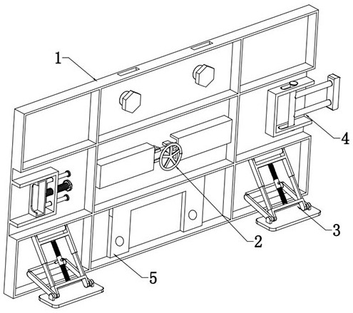
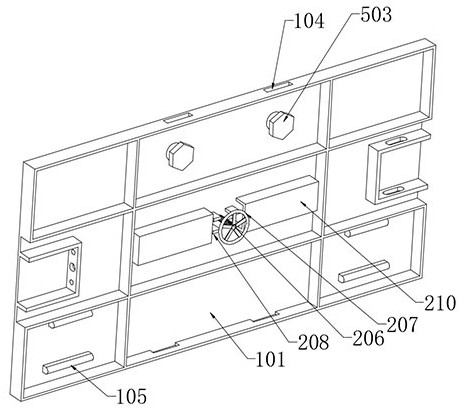
[0035] like Figure 1 to Figure 11 As shown, a steel structure formwork for construction includes a formwork body 1, a separation component 2, a support component 3, a horizontal connection component 4 and a vertical connection component 5. The middle of the formwork body 1 is provided with a separation component 2. Two symmetrically distributed support assemblies 3 are arranged at the bottom end of the side surface, horizontal connection assemblies 4 are arranged on both sides of the outer side of the formwork body 1, and vertical connection assemblies 5 are arranged in the middle of both ends of the outer side of the formwork body 1;

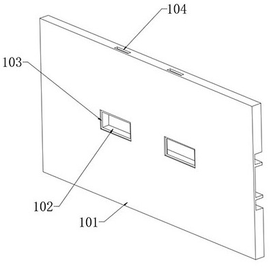
[0036] Formwork body 1. Formwork body 1 includes a fixing plate 101. Two symmetrically distributed square grooves 102 are formed through the middle of the inner side of the fixing plate 101. A groove 103 is formed at the notch of the square groove 102. Two symmetrically distributed slots 104 are provided through the fixing plate 101 , and two ...

no. 2 example

[0049] like Figure 12 As shown in the figure, after the device is spliced ​​and concrete is poured between the steel structure formwork, there will be a large amount of gas inside the concrete. If the gas cannot be discharged in time, cracks will appear in the solidified concrete, and the concrete will During the solidification process, its volume will shrink. If the steel structure formwork cannot adjust its gap correspondingly with the change of the concrete volume, it will cause cracks in the solidified concrete and reduce the strength and aesthetics of the concrete structure. The exhaust effect and the adaptive adjustment effect when the concrete is poured and solidified, the steel structure formwork for building also includes: the outer surface of the push plate 203 is provided with a pressure sensor, and the pressure of the concrete on the outer surface of the push plate 203 can be effectively detected by means of the sensor. value.

[0050] The inner bottom of the con...


PUM


Abstract

The invention discloses a steel structure formwork for building, and relates to the technical field of building auxiliary devices, the steel structure formwork comprises a formwork body, a separating assembly, supporting assemblies, a horizontal connecting assembly and a vertical connecting assembly, the separating assembly is arranged in the middle of the formwork body, and the two supporting assemblies which are symmetrically distributed are arranged at the bottom end of the outer side face of the formwork body. According to the concrete formwork, the formwork body is arranged, the separation assembly is arranged in the middle of the formwork body, the formwork body can be more conveniently separated from formed concrete through the arrangement of the separation assembly, the supporting assembly is arranged at the bottom end of the outer side of the formwork body, and the formwork body is conveniently placed and fixed through the arrangement of the supporting assembly; and by arranging the horizontal connecting assemblies and the vertical connecting assemblies, splicing and assembling of the multiple formwork bodies are facilitated, and then using of the device is facilitated.

Description

technical field [0001] The invention relates to the technical field of construction auxiliary devices, in particular to a steel structure formwork for construction. Background technique [0002] Construction engineering refers to the engineering entity formed through the construction of various housing buildings and their ancillary facilities and the installation of their supporting lines, pipelines, and equipment. And projects that can form internal spaces to meet the needs of people's production, living, learning, and public activities. [0003] Steel formwork is a steel formwork used for concrete casting. In addition to steel formwork, there are also wooden formwork, plywood formwork, etc. [0004] Chinese invention patent 2020106603722 discloses a prefabricated formwork for a steel structure for construction, including a wall formwork main body, a first connection slot, a first connection board, a second connection slot, a second connection board and a connection fixing...

Claims


Application Information

Patent Timeline
Patent Type & Authority Applications(China)
IPC IPC(8): E04G17/04E04G17/00E04G21/06
CPCE04G17/047E04G17/001E04G21/065
Inventor 康晓杰张占权李志凯唐永纲任登巍曹日旭曹一明王磊黄志强
Owner SHANXI INSTALLATION GRP CO LTD
Learn More