
Pipe explosion simulation device based on fluid blocking test and test method thereof

A simulation device and tube squib technology, which is applied in the field of fluid blocking test, can solve problems such as difficult control of tube squib time, inability to meet millisecond-level test requirements, slow action time, etc., to achieve convenient and reliable operation, compact and reasonable structure, and precision sex high effect

Pending Publication Date: 2022-07-29
HEFEI GENERAL MACHINERY RES INST +1
View PDF0 Cites 0 Cited by
  • Summary
  • Abstract
  • Description
  • Claims
  • Application Information

AI Technical Summary

Problems solved by technology

However, due to real pipe burst accidents, the initial dehydration spraying time is about milliseconds, and the burst pipe simulation devices used in the existing public fluid blocking test technology are all conventional single-diaphragm structures, and the action time is slow and explosive. The tube time is difficult to control, obviously unable to meet the test requirements of millisecond level, and needs to be solved urgently

Method used

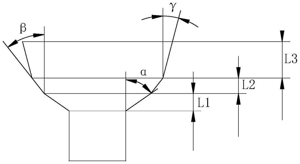

Image

  • Pipe explosion simulation device based on fluid blocking test and test method thereof
  • Pipe explosion simulation device based on fluid blocking test and test method thereof
  • Pipe explosion simulation device based on fluid blocking test and test method thereof

Examples


Embodiment Construction

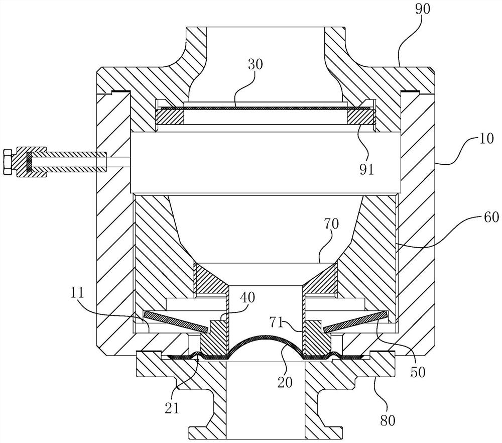
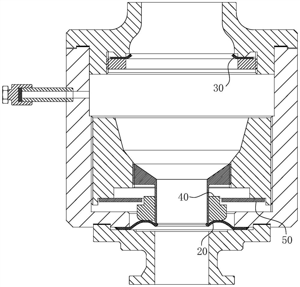
[0037] For ease of understanding, here Figure 1-6 , the concrete structure of the present invention and working mode are further described below:

[0038] The specific structure of the present invention is as follows Figure 1-2 As shown, the outer tube body 10 is used as the carrier, and the bottom end face of the outer tube body 10 is arranged with a closing 11 to form a plunger cylinder shape as a whole, and in the cylindrical cavity of the outer tube body 10 as shown in the figure figure 1 As shown, the inlet ring cover 80, the crushing diaphragm 20, the diaphragm pressing ring 40, the disc spring 50, the diaphragm supporting ring 70 with the extension tube 71, the spring base 60, the upper pressing ring, Rupture disc 30 and outlet ring cover 90. Of course, the bursting disc 30 is used as a standard part, and the existing mature bursting disc 30 products can be reasonably selected according to the test parameters, and it is not limited to a specific structural form. in...


PUM


Abstract

The invention belongs to the technical field of fluid blocking tests, and particularly relates to a pipe burst simulation device based on a fluid blocking test and a test method of the pipe burst simulation device. The pipe bursting simulation device comprises an outer pipe body and a crushing diaphragm located in a pipe cavity of the outer pipe body, the device further comprises a bursting disc, the bursting disc and the crushing diaphragm are sequentially arranged along the pipe cavity of the outer pipe body, and therefore a closed pressure adjusting cavity is formed between one section of the pipe cavity of the outer pipe body between the bursting disc and the crushing diaphragm. The pressure adjusting cavity is communicated with a pressure air source or a pressure liquid source through a flow channel penetrating through the pipe wall of the outer pipe body. The device has higher controllability on pipe explosion pressure and pipe explosion time, and has the advantages of simplicity, convenience and rapidness in use and compact and reasonable structure.

Description

technical field [0001] The invention belongs to the technical field of fluid blocking test, in particular to a pipe burst simulation device based on a fluid blocking test and a test method thereof. Background technique [0002] The purpose of the fluid blocking test is to determine the key performance parameters of the check valve, to verify the emergency shut-off capability of the valve after the reverse flow occurs under the condition of a water loss accident in a nuclear power plant, and to be conservative enough to the pipeline pressure fluctuation level caused by the instantaneous closure of the valve 's estimate. In the fluid blocking test, a pipe burst simulation device is required to meet the requirements of water loss spraying. The basic principle of the traditional burst pipe simulation device is to use a certain kind of diaphragm, and fix the diaphragm between the outlet of the intake port and the high-pressure gas supply pipeline, and the diaphragm ruptures to f...

Claims


Application Information

Patent Timeline
Patent Type & Authority Applications(China)
IPC IPC(8): F15C3/04F16K17/16G01M13/003
CPCF15C3/04F16K17/16G01M13/003
Inventor 范宜霖王剑张继伟黄健彭林雷艳李忠冯玉林
Owner HEFEI GENERAL MACHINERY RES INST
Learn More