Coal mine sump sludge thickness measuring device and measuring method
A technology for thickness measurement and silt, applied in the field of silt thickness measurement device for coal mine water silo, can solve the problems of high silt density, inconvenient use, cumbersome operation, etc. Effect
- Summary
- Abstract
- Description
- Claims
- Application Information
AI Technical Summary
Problems solved by technology
Method used
Image
Examples
Embodiment 1
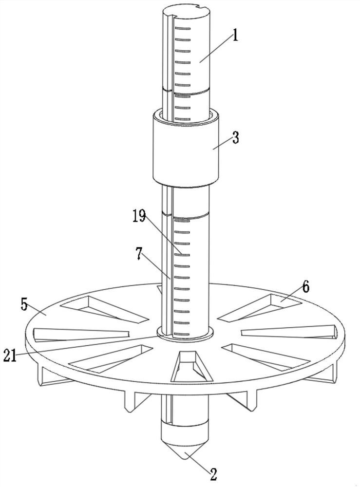
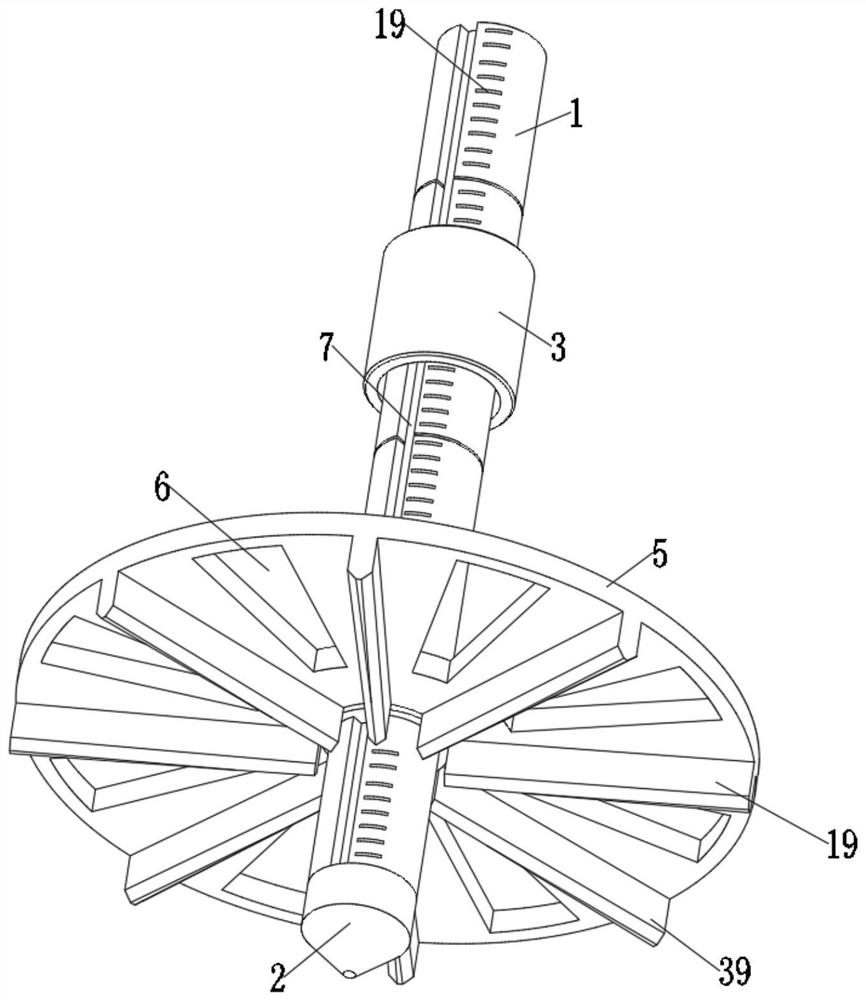
[0035] see Figure 1-6 , and discloses a coal mine water silo silt thickness measurement device and a measurement method, wherein a coal mine silo silt thickness measurement device includes a support shaft 1 and a height limit plate 5 outside the support shaft 1, and the lower end of the support shaft 1 is installed There is a conical head 2, a support outer ring 21 is arranged inside the height limit plate 5, a rotating inner ring 31 is installed inside the supporting outer ring 21, a positioning pin 32 is arranged on the inner wall of the rotating inner ring 31, and an outer side of the support shaft 1 is arranged. There is a positioning chute 7, a positioning pin 32 is used to connect the chute in the positioning chute 7, a contact shaft 22 is installed inside the support shaft 1, a third spring 27 is installed at the lower end of the contact shaft 22, and the inner part of the limit sleeve 3 The limit inner ring 23 is installed, the outer side of the contact shaft 22 is pr...
Embodiment 2
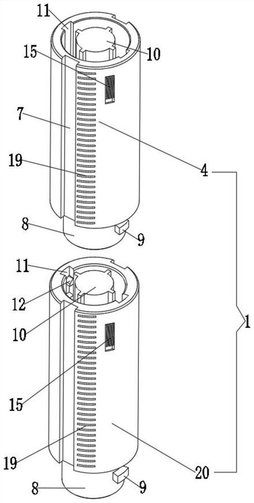
[0042] This embodiment is an improvement made on the basis of Embodiment 1. For details, please refer to Figure 1-6 , the support shaft 1 includes a first combined shaft 4 and a second combined shaft 20, the lower end of the first combined shaft 4 is mounted with a second combined shaft 20, the lower end of the first combined shaft 4 is also provided with an extension end 8, the interior of the extended end 8 There is an internal control groove 17, the inner wall of the internal control groove 17 is provided with a clamping groove 18, the upper ends of the first combined shaft 4 and the second combined shaft 20 are provided with positioning piles 10, and the upper ends of the first combined shaft 4 and the second combined shaft 20 are provided with positioning piles 10. Each is provided with a limiting wall groove 11 , and a detent block 9 is provided on the outer side of the extension end 8 , and the detent block 9 is used to be clamped in the limiting wall groove 11 .
[00...
Embodiment 3
[0045] This embodiment is an improvement made on the basis of Embodiment 2. For details, please refer to Figure 1-6 , the support shaft 1 is also provided with a fixed bayonet 12 located in the limit wall groove 11, the upper end of the fixed bayonet 12 is provided with an inclined slot 13, one end of the fixed bayonet 12 is installed with a first spring 14, the fixed bayonet The upper end of 12 is installed with a toggle slider 15 located outside the first combination shaft 4 , and the inner side of the toggle slider 15 is provided with a pressing end 16 .
[0046] When the first combined shaft 4 and the second combined shaft 20 are connected end to end, the bayonet block 9 will be snapped into the limiting wall groove 11 , and the outer side of the bayonet block 9 will be in contact with one end of the fixed bayonet 12 when it is snapped in. , and squeeze the fixed bayonet 12 to the inner side of the limit wall groove 11, so that the bayonet block 9 is completely embedded i...
PUM
 Abstract
Description
Claims
Application Information
 - R&D
- Intellectual Property
- Life Sciences
- Materials
- Tech Scout
- Unparalleled Data Quality
- Higher Quality Content
- 60% Fewer Hallucinations
Browse by: Latest US Patents, China's latest patents, Technical Efficacy Thesaurus, Application Domain, Technology Topic, Popular Technical Reports.
© 2025 PatSnap. All rights reserved.Legal|Privacy policy|Modern Slavery Act Transparency Statement|Sitemap|About US| Contact US: help@patsnap.com


