Method and system for measuring reverse friction of vehicle steering system

A technology of steering system and reverse friction, which is applied in the direction of vehicle steering/bump performance, can solve the problems of high cost and complicated operation of measurement methods, and achieve the effect of low cost, strong operability and simple structure

Active Publication Date: 2015-06-24
ZHENGZHOU YUTONG BUS CO LTD
View PDF8 Cites 3 Cited by
  • Summary
  • Abstract
  • Description
  • Claims
  • Application Information

AI Technical Summary

Problems solved by technology

[0004] The purpose of the present invention is to provide a method and system for inverse friction measurement of automobile steering system to solve the problems of complicated operation and high cost of existing measurement methods

Method used


Image

  • Method and system for measuring reverse friction of vehicle steering system
  • Method and system for measuring reverse friction of vehicle steering system
  • Method and system for measuring reverse friction of vehicle steering system

Examples


Embodiment 1

[0029] An inverse friction measurement system for a vehicle steering system of the present invention, its basic composition and connection method are: at least one power device for providing steering torque, a turntable for driving the wheels to rotate synchronously, and for measuring the rotation angle of the wheels and measuring The power device is a measurement unit for outputting driving torque, and a processing operation unit for processing the data collected by the measurement unit, and the power device drives and connects the turntable.

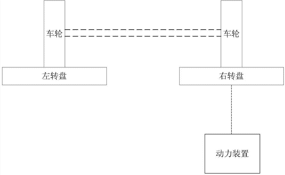
[0030] Such as figure 1 As shown, it mainly includes two turntables corresponding to the wheels on the same axle of the vehicle to be tested, and a power unit. The power unit is connected to the left turntable or right turntable.

[0031] First, the power unit is driven and connected to one of the turntables, and the other turntable can rotate freely, placing the front wheels of the vehicle on the left and right turntables respectively...

Embodiment 2

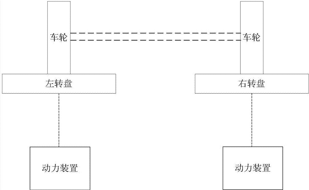
[0040] Such as figure 2 As mentioned above, the only difference from Embodiment 1 is that it includes two power units and left and right turntables corresponding to the left and right wheels on the same axle of the vehicle to be tested, and each power unit is respectively driven and connected to the left and right turntables.

[0041] The specific implementation process is similar to that of Embodiment 1, and the similar parts will not be repeated here.

[0042] Specifically, compared with the calculation formula of the reverse friction torque in embodiment 1, the calculation formula of the reverse friction torque in embodiment 2 also needs to be changed correspondingly, the reverse friction torque: M=i*η*(M0 左 +M0 右 )-f*G*r.

Embodiment 3

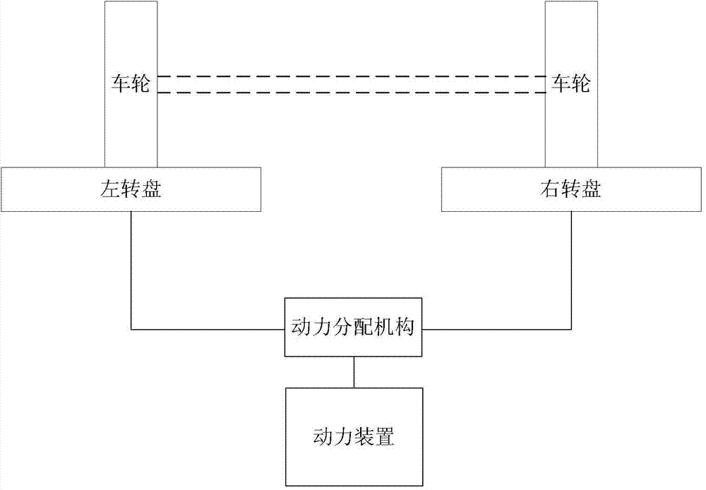
[0044] Such as image 3 As mentioned above, the only difference from Embodiment 1 is that it includes a power unit and left and right turntables corresponding to the left and right wheels on the same axle of the vehicle to be tested, and the power unit is connected to the two turntables through a power distribution mechanism.

[0045] The specific implementation process is similar to the first embodiment, and the similar parts will not be repeated here.


PUM


Abstract

The invention relates to a method and system for measuring reverse friction of a vehicle steering system. The method for measuring the reverse friction of the vehicle steering system comprises the steps that a rotary disc is fixed with wheels of a vehicle to be detected, driving force is applied to the rotary disc, the rotary disc drives the wheels to rotate, the rotating angle of the wheels is recorded when the wheels do not rotate any more under the driving force, and the reverse friction force of the vehicle steering system under the rotating angle of the wheels is obtained through the driving force and the resistance force borne by the rotary disc in the rotating process. Compared with a traditional vehicle steering reverse friction torque measuring method, according to the scheme, manpower is saved, and meanwhile steering detection can be carried out on the vehicle with high efficiency and high precision. In addition, equipment in the scheme is high in operability and low in cost, measured data can provide supports for the steering reversal performance of a product, and inconsistency of product quality is avoided.

Description

technical field [0001] The invention relates to a method and system for inverse friction measurement of a vehicle steering system. Background technique [0002] The steering return performance of the vehicle is related to the driving comfort and controllability of the vehicle, and directly affects the safe driving of the vehicle, and the reverse friction of the steering system is an important factor affecting the steering return performance of the vehicle; under the same suspension positioning parameters, the steering The difference in the reverse friction of the system will cause the difference in the performance of the vehicle, such as the return performance and the magnitude of the operating force. Especially for batch vehicles, the difference in quality will directly affect the market evaluation of the product. The driver's operation is laborious and other disadvantages; at present, there is no convenient and quick tool to cooperate with the production line to check the ...

Claims


Application Information

Patent Timeline
Patent Type & Authority Applications(China)
IPC IPC(8): G01M17/06
Inventor 樊金磊叶帅秦涛段海涛
Owner ZHENGZHOU YUTONG BUS CO LTD
Why Eureka
Try Eureka